
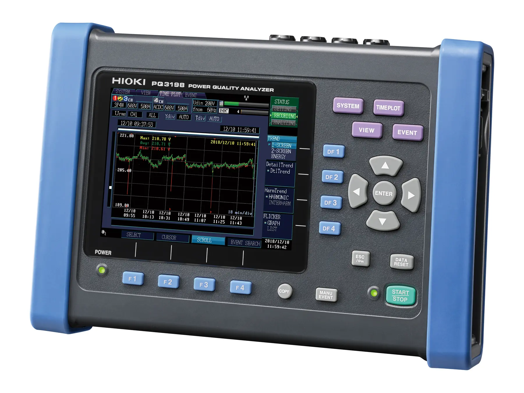
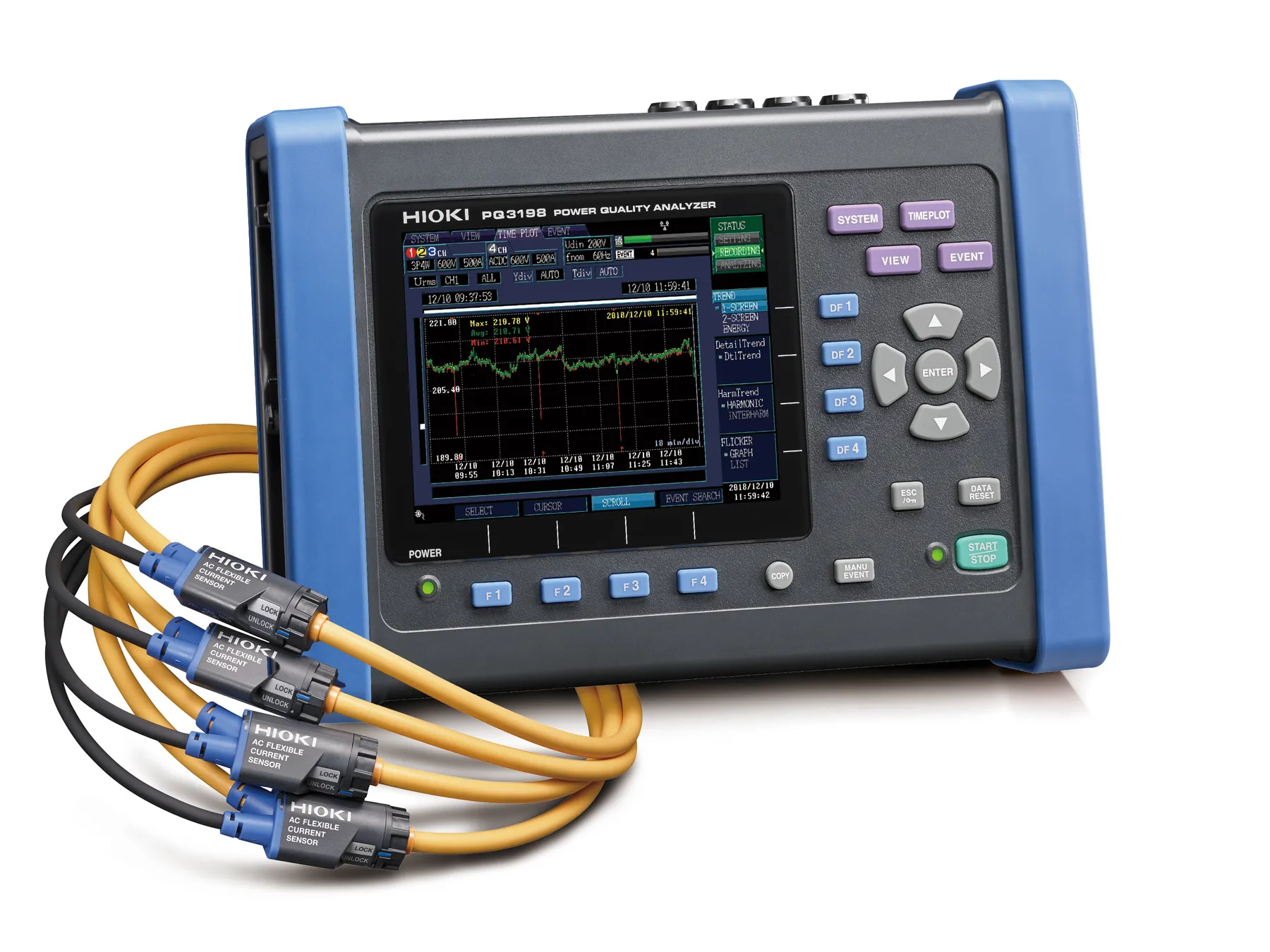
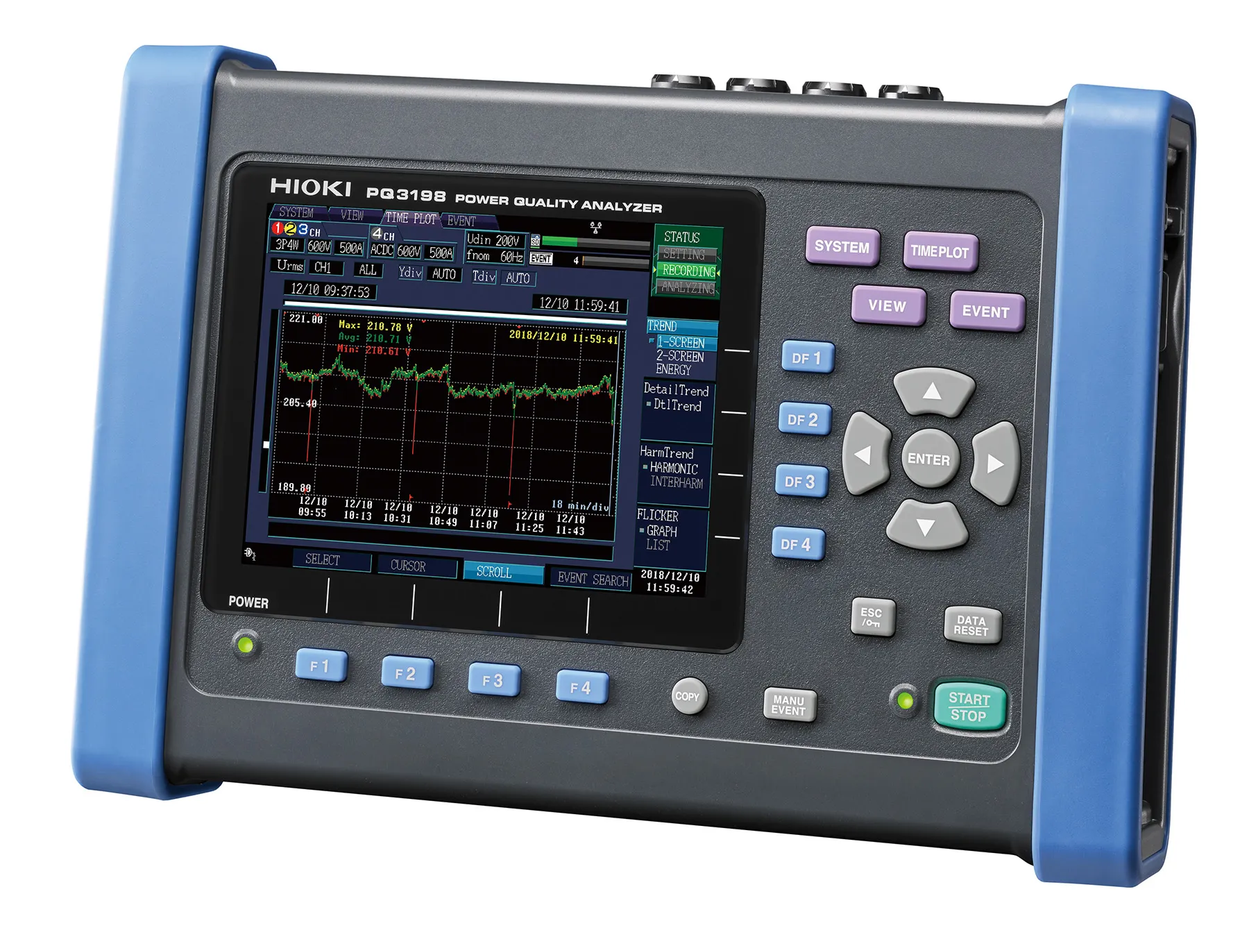
PQ3198 - Class A Power Quality Analyzer with Isolated Fourth Channel
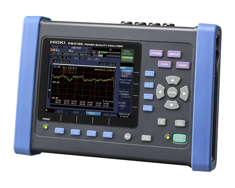
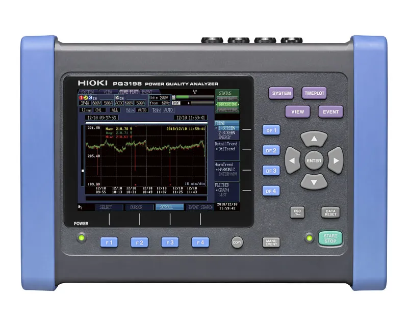


Product information PQ3198 - Class A Power Quality Analyzer with Isolated Fourth Channel
Key Specifications
- IEC 61000-4-30 Class A
- Isolated CH4: second system, AC or DC
- Simultaneous trend and event recording
- Supraharmonics 2–80 kHz, transients 6 kV
- CAT IV 600 V
Typical Applications
- Load tests during data center commissioning: UPS, standby generators, load steps
- Voltage quality assessment to EN 50160
- Tracing the causes of voltage dips, transients and equipment trips
- Investigating harmonics and supraharmonics from inverters and EV chargers
- Long-term power quality monitoring in industrial power distribution
- Power and efficiency measurement on inverters across two systems
Detailed Product Overview
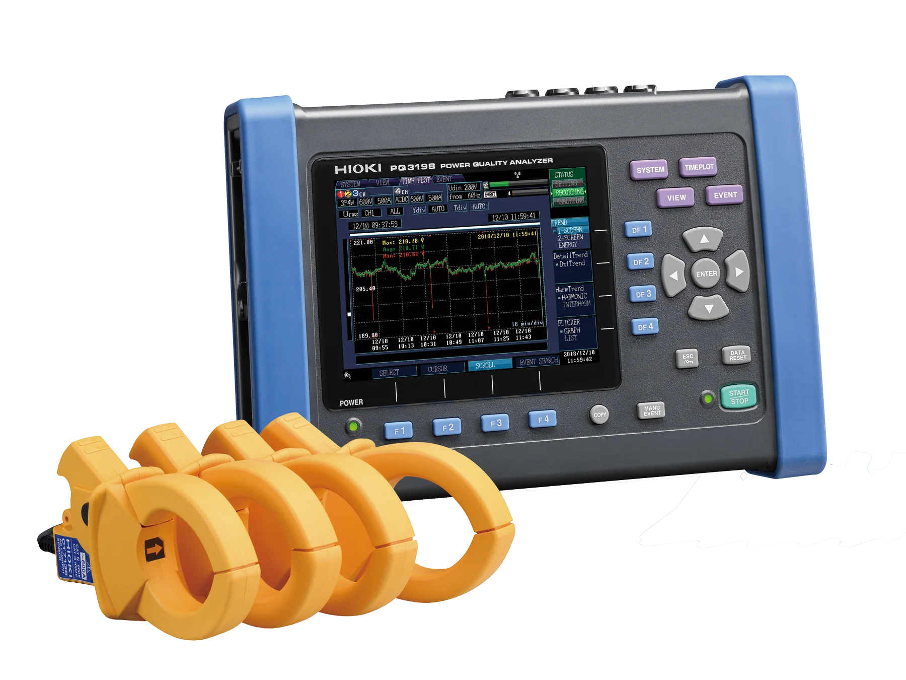
When a data center is commissioned, its UPS systems and standby generators have to prove under load that they switch over cleanly. The HIOKI PQ3198, a Class A power quality analyzer to IEC 61000-4-30, documents exactly that: it follows voltage and frequency through every transfer and load step, recording trends and events in one gap-free measurement. Troubleshooting and standards-based voltage quality assessments are just as much part of its job.
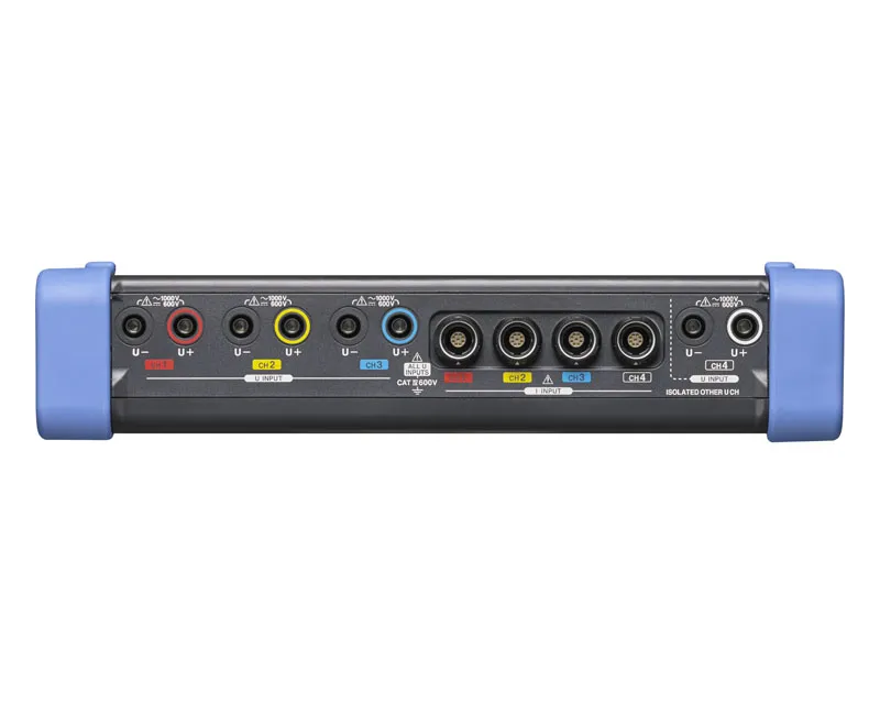
The analyzer has four voltage and four current channels. Channels 1 to 3 cover single-phase systems through to three-phase four-wire, and channel 4, isolated from them, is free for the neutral or for a separate circuit, including DC. Measurement data goes to an SD card; a 2 GB card comes with the instrument. Current sensors are not supplied, so they can be ordered to match the job.
Load tests during commissioning
A typical test sequence switches off the mains, lets the UPS bridge the gap, brings the standby generator online and finally returns to the grid, often with load steps in between. The PQ3198 keeps recording the trend throughout and captures each of these moments as an event. For dips, swells, interruptions and inrush currents, it stores half-cycle RMS values covering 0.5 s before to 29.5 s after the trigger, along with the waveform of a 200 ms window and two cycles either side, so cause and response sit in a single data set.
Because the analyzer runs on its Z1003 Battery Pack for about 3 hours, a deliberate blackout does not end the recording. Generator behavior after a load step, meaning how far the frequency falls and how fast it settles, shows up in the frequency measured over each cycle, with 200 ms and 10 s values available too. Quick setup and the wiring check speed up the move from one measuring point to the next, and PQ ONE produces the reports for the acceptance documentation.
Measuring two systems at once
On most power quality analyzers, channel 4 is reserved for the neutral. On the PQ3198, it is galvanically isolated from channels 1 to 3, which means it can also measure a second, entirely separate system, AC or DC, simultaneously with the three-phase measurement. In a three-phase four-wire system, it does the usual job and measures neutral current and neutral-to-earth voltage.
A second instrument is often unnecessary as a result. The PQ3198 works out the power on both sides and the efficiency between them, for instance on inverters with fundamental frequencies of 40 Hz to 70 Hz and carrier frequencies up to 20 kHz, where an AC/DC sensor on channel 4 picks up the DC side. It can also keep an eye on DC supplies while monitoring the AC network, down to equipment-internal rails of ±24 V, ±15 V or ±5 V. Because changes in DC quantities trigger events too, a disturbance on one side can be linked to its effect on the other.
Events and recording time
Event triggers include transients, swells, dips, interruptions, frequency fluctuations and inrush currents, as well as limit violations for RMS values, peaks, harmonics, supraharmonics, THD, unbalance, power and mains signaling voltage. A waveform comparison detects deviations from the previous voltage waveform, and external signals at the EVENT IN terminal can set events or start and stop recording.
Each measurement holds up to 9999 events; with daily repeat recording, that limit applies per day for up to 366 days, and weekly repeat recording extends a measurement to as long as 55 weeks. Recording intervals range from 1 s to 2 h, alongside the 150-cycle (50 Hz) and 180-cycle (60 Hz) intervals specified by the standard. Data goes straight to the SD card, and the Z4003 card with 8 GB is available for long-term measurements.
Disturbances an RMS trend misses
Switching operations produce voltage spikes far too short to show up in RMS values. To capture them, the PQ3198 samples voltage at 2 MS/s and detects transients up to 6 kV peak in the 5 kHz to 700 kHz range, from a duration of 0.5 µs. For each transient, it keeps the waveform from 2 ms before to 2 ms after.
Above the classic harmonic range, inverters, switch-mode power supplies and EV chargers emit supraharmonics, which wiring resonances can amplify to more than 10 V. The PQ3198 measures them in both voltage and current from 2 kHz to 80 kHz. Harmonics of voltage, current and power are captured from the 0th to the 50th order with phase angles, interharmonics from order 0.5 to 49.5, together with THD. Comparing the phase angles of harmonic voltage and current reveals the direction in which a harmonic flows, and thus whether it originates in the supply network or in the installation itself.
Class A and what it guarantees
IEC 61000-4-30 Class A prescribes the measurement method, the aggregation and the accuracy for every parameter. That is what makes results comparable, no matter who measured, where or when. The PQ3198 complies with Class A of Edition 3 (2015) and also measures in accordance with IEEE 1159.
Voltage accuracy at 50/60 Hz is ±0.1 % of nominal voltage. Current accuracy is ±0.1 % rdg. ±0.1 % f.s. and active power accuracy ±0.2 % rdg. ±0.1 % f.s., each with the current sensor's accuracy added, and frequency over 200 ms is measured to ±0.02 Hz. HIOKI guarantees these values for one year. Voltages up to 600 V can be measured, and with its CAT IV 600 V rating, the PQ3198 is approved for measurements at the service entrance and the incoming supply.
Sampling runs at 200 kHz for voltage and current. Among the parameters are RMS and halfcycle RMS values, peaks, frequency over one cycle, 200 ms and 10 s, active, reactive and apparent power, power factor, unbalance and K factor. Active energy is metered separately for consumption and regeneration. Flicker (Pst and Plt to IEC 61000-4-15, plus ΔV10) and mains signaling voltage complete the picture. Besides 50 Hz and 60 Hz systems, 400 Hz systems can be measured too.
Choosing current sensors
Current and power measurements need current sensors: one for single-phase two-wire, two or three for three-phase systems depending on the wiring, and one more if channel 4 is used. Which model fits depends on the conductor, the current level and the space around the measuring point.
Most users opt for four CT7136 AC clamp-on sensors, with three on the phases and one on the neutral via channel 4. They are rated 600 A, accept conductors with a diameter of up to 46 mm and meet CAT IV 600 V just like the analyzer. Where a flexible sensor is preferred, the CT7045 is the most frequent pick: 6000 A rated current and a loop for conductors up to 180 mm across.
Each sensor type has its strengths. AC clamp-on sensors go on in seconds; flexible sensors get into tight spots and around large conductors; AC/DC auto-zero clamp-on sensors add DC and stay stable over long measurements. The CT7116 is intended for leakage and protective earth currents, not for power measurement. All sensors in the table have a PL14 connector, and a key press is all the PQ3198 needs to recognize and configure them.
Since the PQ3198 supplies power to the AC/DC and flexible sensors, they need no batteries, and none can run flat even over weeks of measurement. For supraharmonics in the current, the limiting factor is the sensor bandwidth. The CT7126 and CT7131 are rated CAT III 300 V and therefore out of the question for CAT IV measurements. With L0220 Extension Cables, the AC/DC sensors can be placed 2 m further from the instrument and all other sensors 10 m.
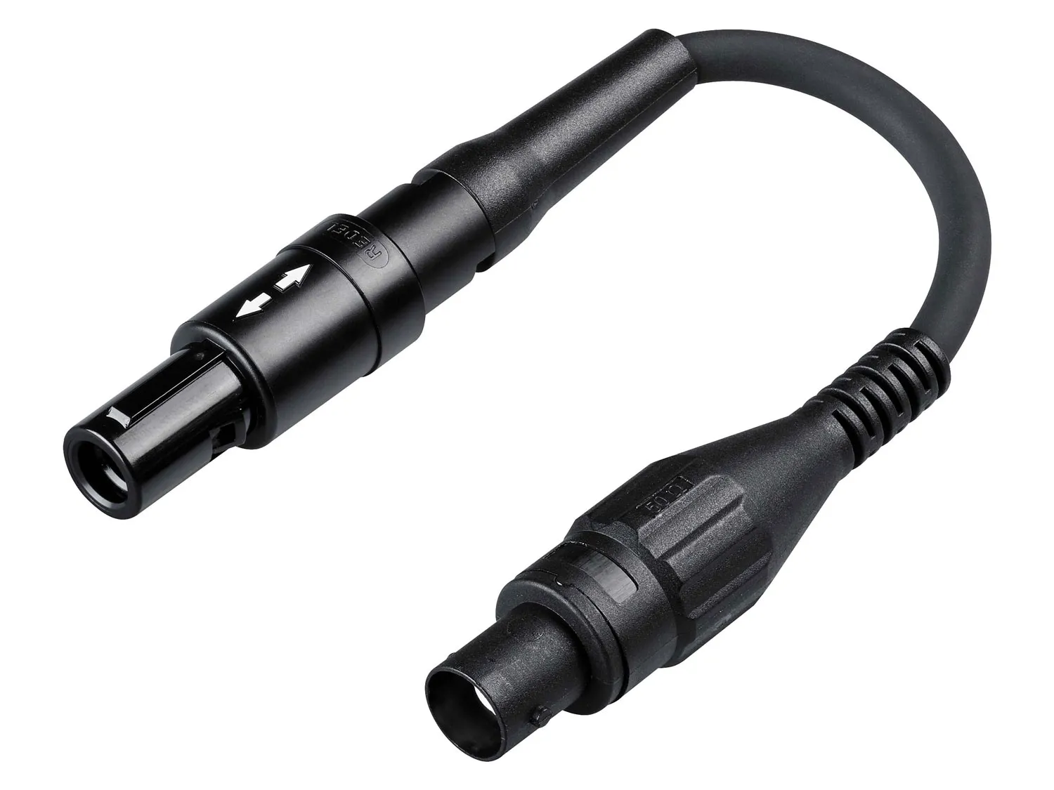
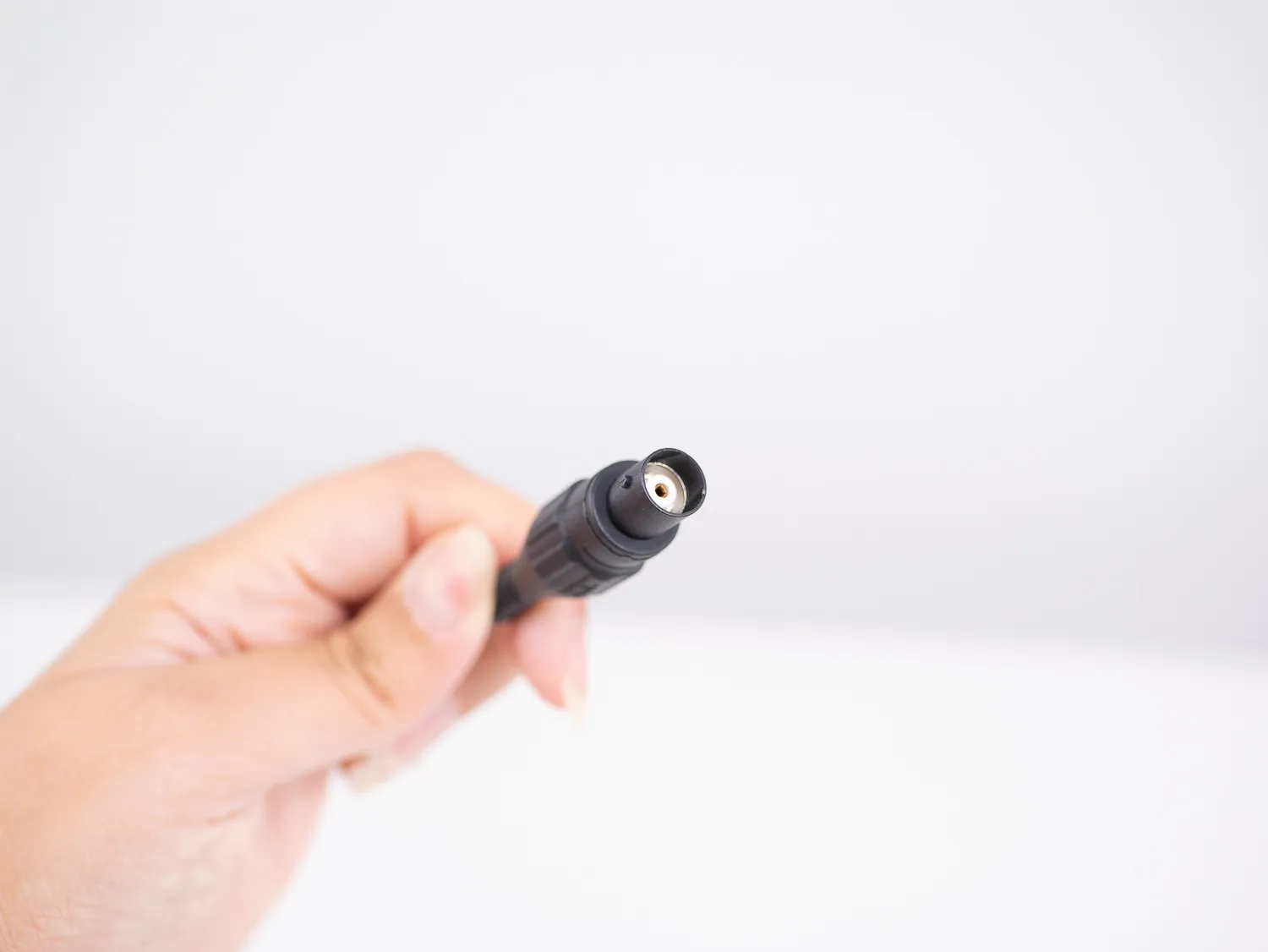
HIOKI sensors with BNC output that are already in use, for example the 9669 for up to 1000 A, the 9657-10 and 9675 leakage sensors or the CT9667 flexible sensor, connect through the L9910 Conversion Cable and are set up manually.
| Model | Type | Rated current | PQ3198 ranges | Bandwidth | Conductor up to Ø |
|---|---|---|---|---|---|
| CT7126 | AC clamp | 60 A | 5 A / 50 A | 40 Hz to 20 kHz | 15 mm |
| CT7131 | 100 A | 50 A / 100 A | |||
| CT7136 | 600 A | 50 A / 500 A | 46 mm | ||
| CT7044 | AC flexible | 6000 A | 50 A / 500 A / 5000 A | 10 Hz to 50 kHz | 100 mm |
| CT7045 | 180 mm | ||||
| CT7046 | 254 mm | ||||
| CT7731 | AC/DC auto-zero | 100 A | 50 A / 100 A | DC to 5 kHz | 33 mm |
| CT7736 | 600 A | 50 A / 500 A | |||
| CT7742 | 2000 A | 500 A / 5000 A | 55 mm | ||
| CT7116 | AC leakage | 6 A | 500 mA / 5 A | 40 Hz to 5 kHz | 40 mm |
On site
Quick setup provides five measurement patterns: voltage events, standard power quality, inrush current, measured-value recording only, and EN 50160. Wiring, current type, recording interval and event thresholds are set accordingly and can be changed afterwards. Before the recording starts, a wiring check verifies the connections, the direction of the current sensors and the phase sequence.
A 6.5-inch color display shows readings and waveforms. With the battery pack fitted, the PQ3198 weighs 2.5 kg, and the Z5020 Magnetic Strap lets it hang from metal surfaces.
Software and remote access
PQ ONE, available from HIOKI as a download, is the PC software for analysis. It shows trends, events and waveforms, and its event counts by day or hour bring clusters at certain times to light. It evaluates measurements against EN 50160 and the ITIC curve, turns screen views directly into reports and exports any section of the data in CSV format.
Connected to a LAN, the PQ3198 works with GENNECT One, which displays live readings and transfers measurement files to the PC automatically. A web browser is enough for remote control via the built-in HTTP server, and measurement data can be downloaded over FTP.
Applications
Beyond the data center, the PQ3198 helps industrial plants find out whether unexplained equipment trips are caused by supply disturbances. At the grid connection of PV and wind power plants, it records voltage and frequency fluctuations, transients and harmonics, and its frequency readings over one cycle, 200 ms and 10 s show how steadily an inverter holds its output frequency. Installed for several weeks, it collects the data needed for a supply quality assessment according to EN 50160.
The PQ3198 was developed by HIOKI in Japan and is manufactured in HIOKI's own plants in Japan.
- PQ3198 Power Quality Analyzer
- L1000 Voltage Cord set (red, yellow, blue, gray, 4 × black; 3 m; 8 alligator clips; 20 spiral tubes)
- Z1002 AC Adapter with power cord
- Z1003 Battery Pack
- USB Cable
- Z4001 SD Memory Card 2 GB
- Instruction Manual
- Measurement Guide
- Operating Precautions
- Color clips for marking current sensors (2 each red, yellow, blue, white)
- Strap
Dimensions & Packaging
| Length | 300 mm |
|---|---|
| Width | 211 mm |
| Height | 68 mm |
| Weight | 2.6 kg |
-
Product Catalog with data sheet, Field Measuring Instruments (English)37,775 KB pdf
-
Product catalog with datasheet, Selection guide, Power Quality Analyzers / Power Loggers (English)3,380 KB pdf
-
Product brochure with data sheet, POWER QUALITY ANALYZER PQ3100, PQ3198 (English)14,258 KB pdf
-
Instruction Manual, POWER QUALITY ANALYZER PQ3198 (English)11,173 KB pdf
-
Instruction Manual, POWER QUALITY ANALYZER PQ3198 (Spanish)11,270 KB pdf
Related Products






How to Purchase Your HIOKI Products
Whether you order directly from HIOKI EUROPE or through an authorized distribution partner: choose the route that fits your procurement process. Our authorized HIOKI partners can assist locally with quotations and orders in your language.
