Accurate High Voltage Power Measurement
Roy Hali
·
16.12.2024
Power Electronics
·
4 min. reading duration
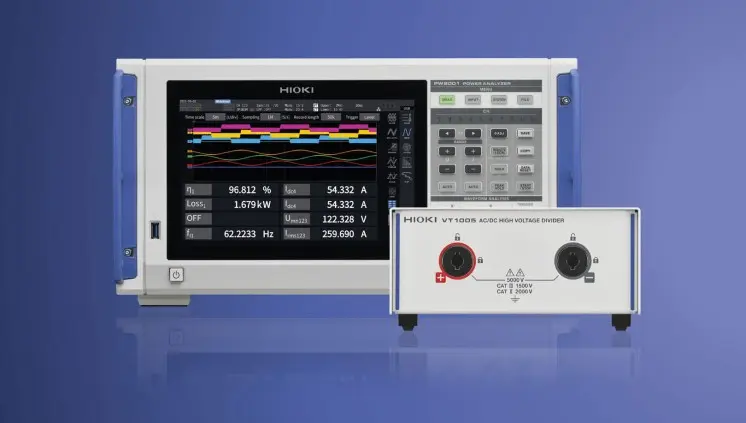
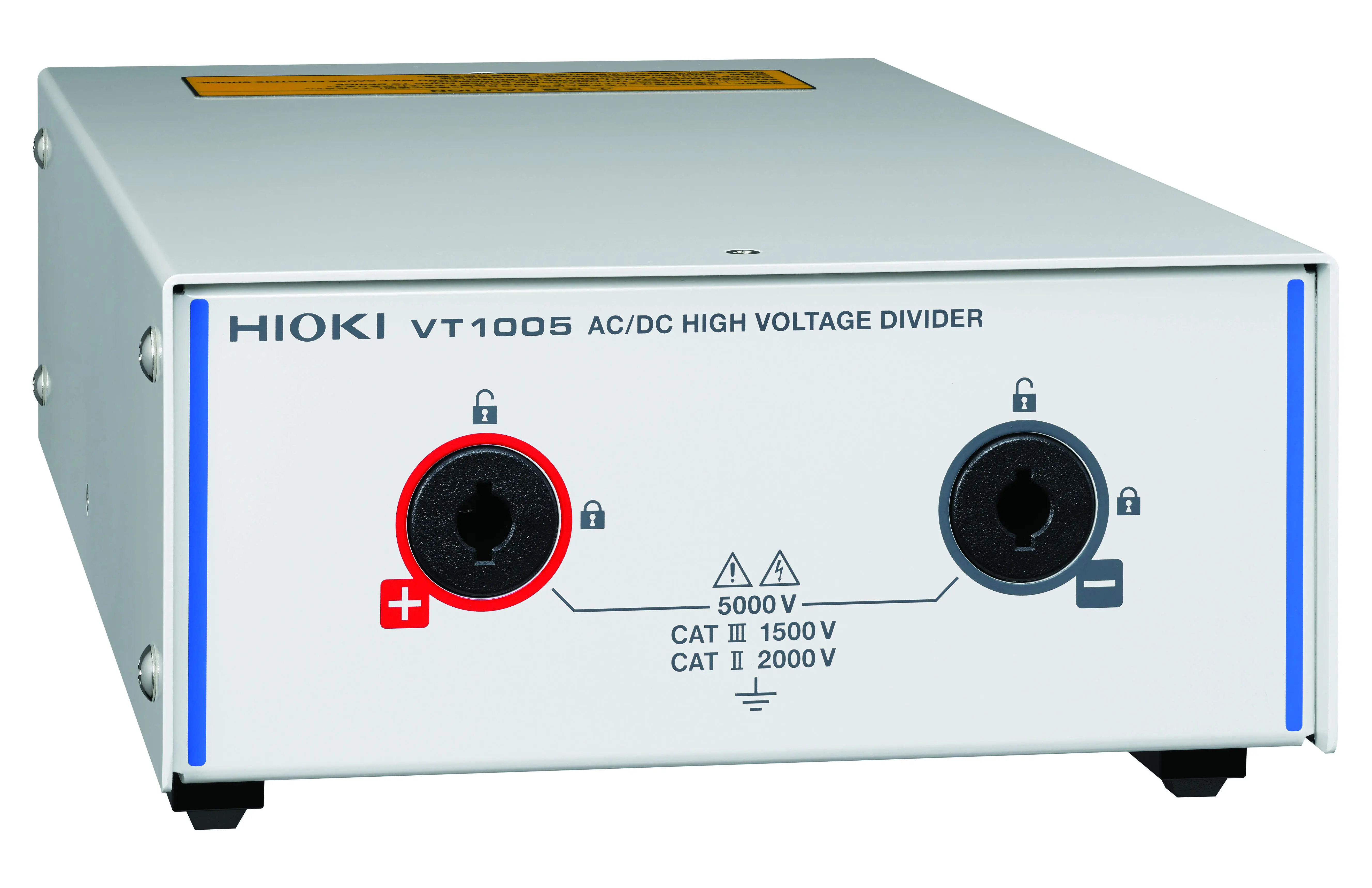
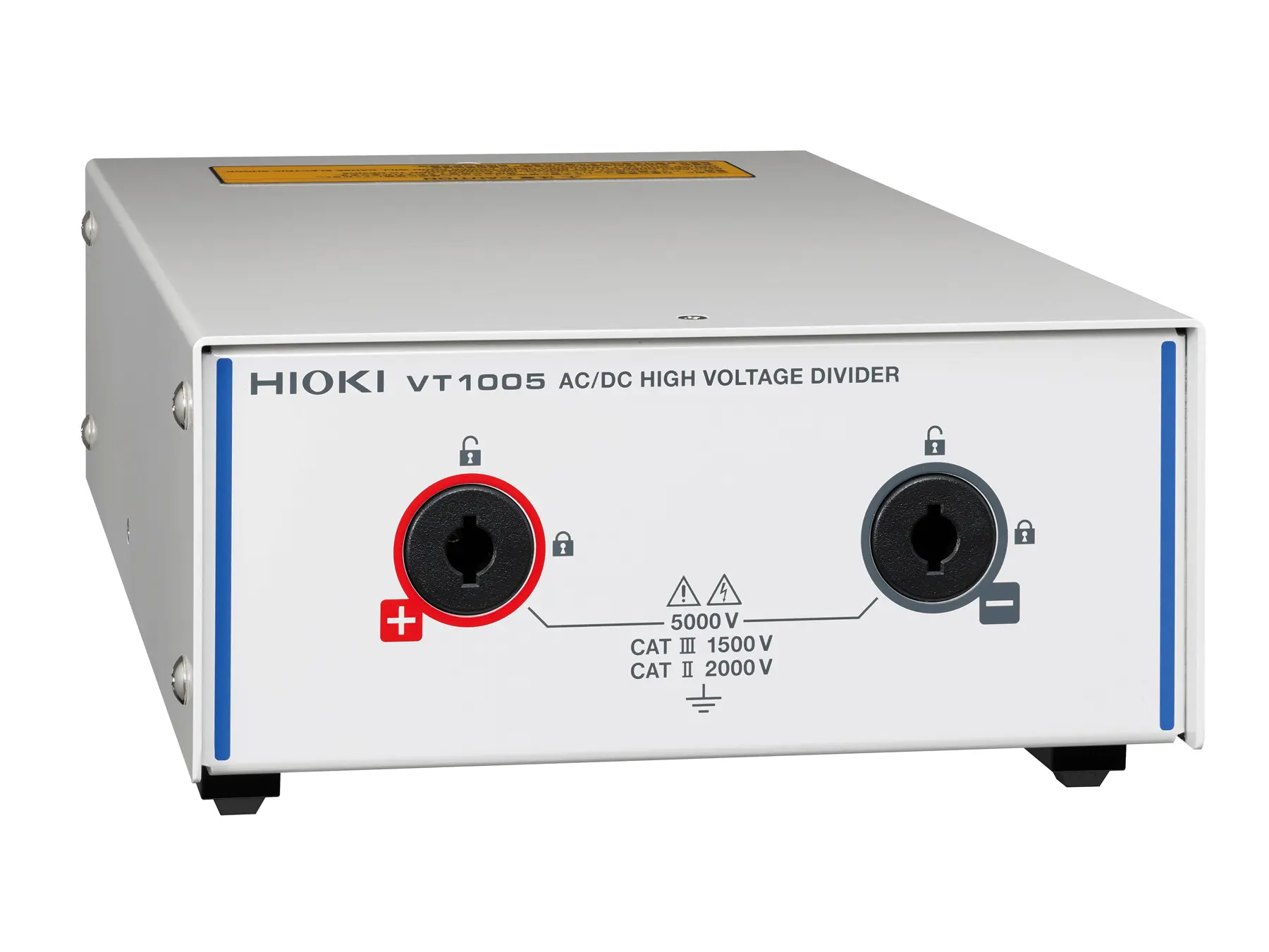
HIOKI’s all new High Voltage Divider VT1005 is an important addition to the HIOKI power measurement solutions. In combination with one of the HIOKI power analyzers, the VT1005 enables to accurately measure power up to 5kV. Especially for high voltage and high frequency applications with SiC and GaN semiconductors, the VT1005 realizes a huge improvement in accuracy over currently available solutions. Additionally, the for loss measurement of HV coils and transformers the new VT1005 is the perfect choice because of its 4 MHz bandwidth.
With ongoing electrification of our society there is a rapidly growing need for more electrical power. One way to meet this need is to increase the system voltage. Obvious applications are the ultra-high-speed chargers for EV’s and all kind of power converters and solid-state transformers to increase the flexibility and reduce the losses of the power grid. Power measurement instruments like for instance the HIOKI PW8001 Power Analyzer can measure power up to a voltage of 1500 Vdc. The VT1005 High Voltage Divider now offers the solution for accurate voltage and power measurements up to 5000 Vrms.
High noise resistivity is essential
The VT1005 is highly resistant to both common-mode and high-frequency noise, allowing it to measure voltage accurately even in noisy environments. Since conversion devices like inverters are sources of noise, noise resistivity is an important factor in power efficiency evaluation. The design of the VT1005 with the floating differential input eliminates common mode noise because the same noise signal will be picked up in both input connection cables and cancelled out in the differential amplifier as it only amplifies the differences at the input.

SiC and even more GaN power devices are characterized by fast voltage rising and falling response, and their output waveforms contain numerous high-frequency components. When we compare the output voltage of the VT1005 with a similar voltage divider on the market, we find that the competitor product shows a “ringing effect” whereas the VT1005 does not. (see fig. 2) Such a ringing effect occurs because the HV input pulses cause parasitic capacitances and inductances in the circuit to resonate at their characteristic frequency. Parasitic capacitances and inductances are not part of the design but just by-products of the components within the circuit layout.
Such a ringing effect though has a negative impact on the accuracy of the voltage and power measurement and therefore must be avoided.
Frequency flatness: manage the increase of your power efficiency
To further increase the efficiency of power systems, SiC and GaN semiconductors are becoming popular switching devices. The switching frequency of SiC semiconductors is 50 kHz or higher, and GaN can even go up to 1 MHz. This makes it hard to accurately measure power efficiency because accuracy must be guaranteed over a broad frequency spectrum from DC up to 1 MHz or even more. To realize such accurate power measurement, HIOKI power measurement systems have excellent frequency flatness, i.e. measurement stability, which enables a constant measurement accuracy over a wide frequency range, which in turn is essential to make targeted increases in efficiency measurable and assessable.
For example, to measure an efficiency improvement of 0.01 %, it is necessary to have a gain accuracy of 0.1 % and the phase error must be within 0.1°.
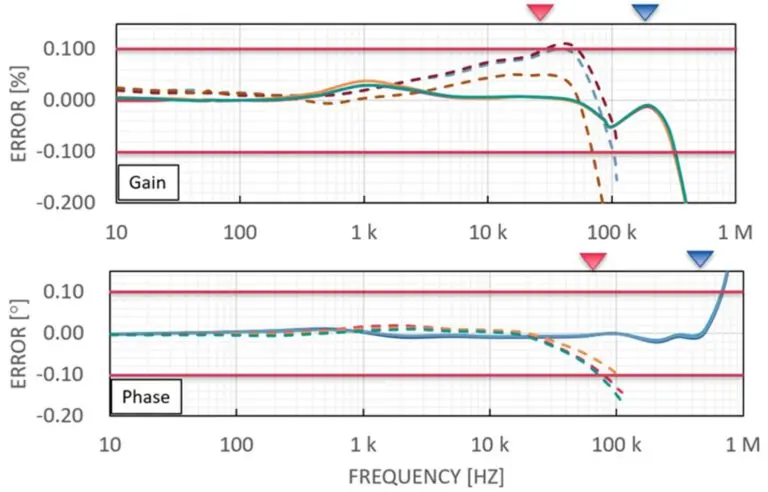
The above two graphs show the gain and phase error for three individual VT1005 and another 3-phase high voltage divider available on the market. What is striking is that you can hardly differentiate the 3 solid lines of the VT1005 as they are almost identical and therefore overlapping whereas the 3 dotted lines of the other voltage divider are much more divergent, indicating that the accuracy is lower. Furthermore, the gain and phase error at higher frequencies are greater with this voltage divider, which makes it unsuitable for applications using SiC or GaN semiconductors.
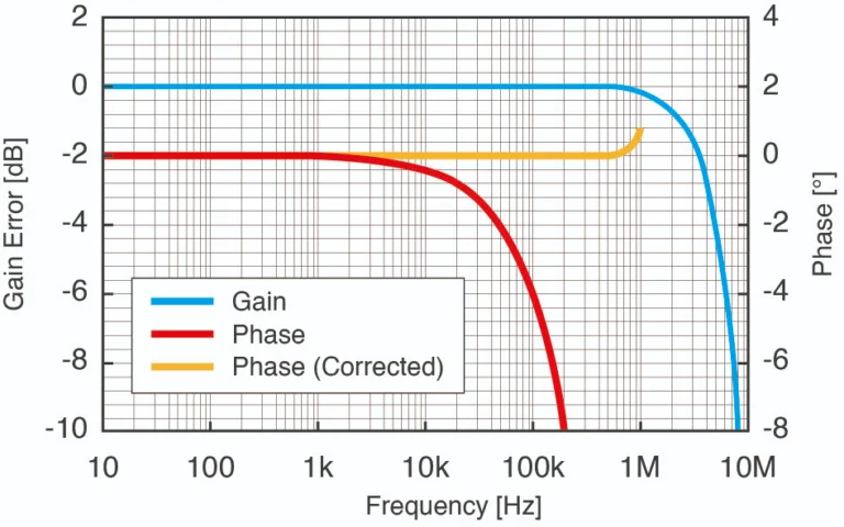
Because both the VT1005 High Voltage Divider and the Current Sensors are designed and produced by HIOKI, they are optimized to be used in combination with the HIOKI Power Analyzers. This allows you to realize outstanding performance both in gain and phase accuracy over the entire frequency range when the phase shift correction function of the power analyzer is activated (see fig.4).
Efficiency measurement for Wireless Power Transfer systems (WPT)
The voltage output of WPT applications tends to be usually up to 3 kV because transmitting power at a higher voltage can reduce power losses during transmission. Therefore, WPT efficiency assessments require an accurate high voltage measurement. Since WPT transfers power through coils, the transmit/receive part has a very low power factor. When the power factor is low, the phase error greatly affects the measured value, so power measurement with a low phase error is essential.
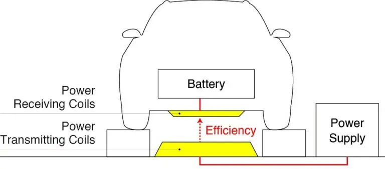
The VT1005’s measurement band ranging from DC to 4 MHz allows to measure voltage from DC to high frequencies. In addition, the excellent flatness of the amplitude and phase characteristics in the measurement band enable highly accurate power measurements and thus accurate evaluation of power efficiency.
Loss measurement of HF inductors and transformers
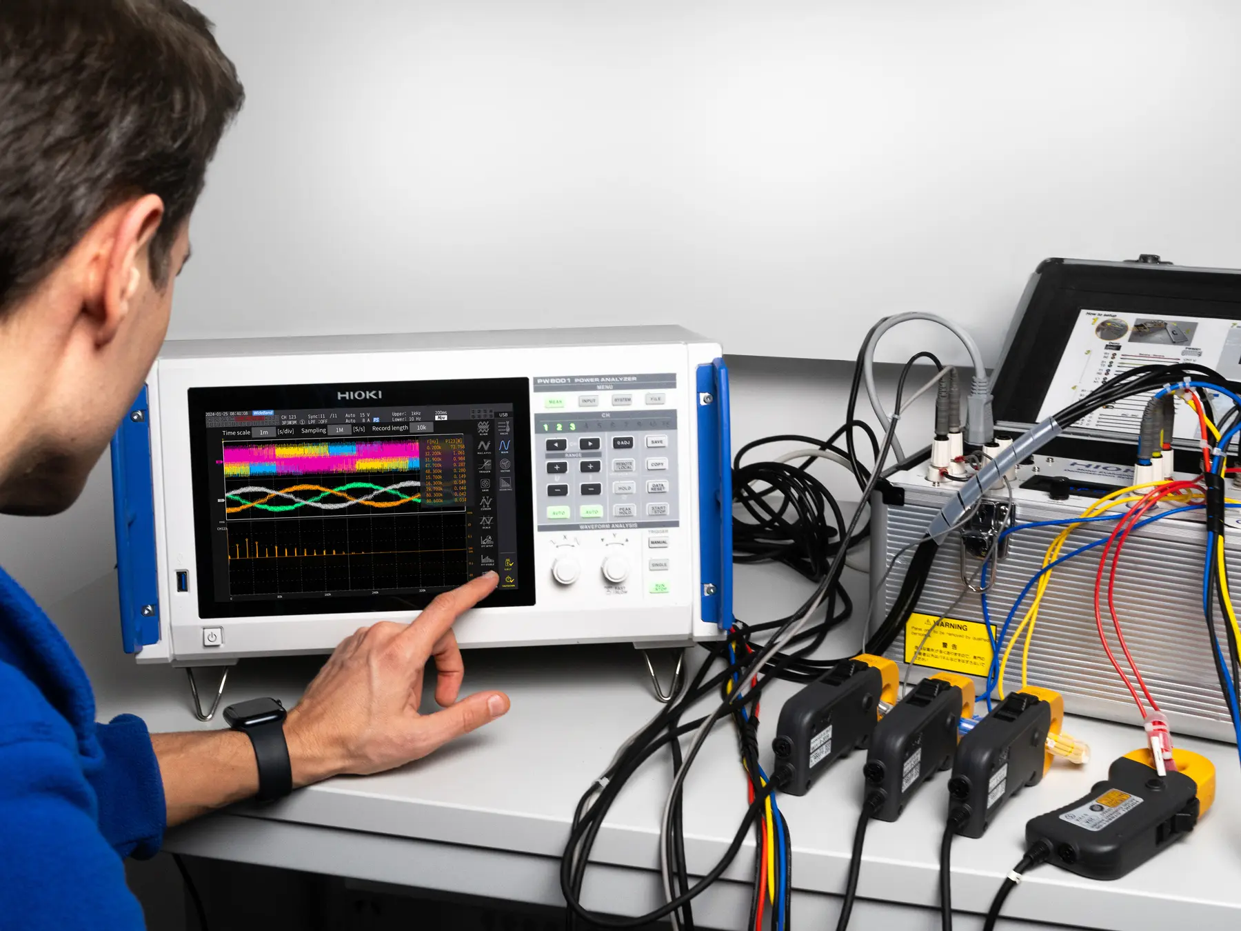
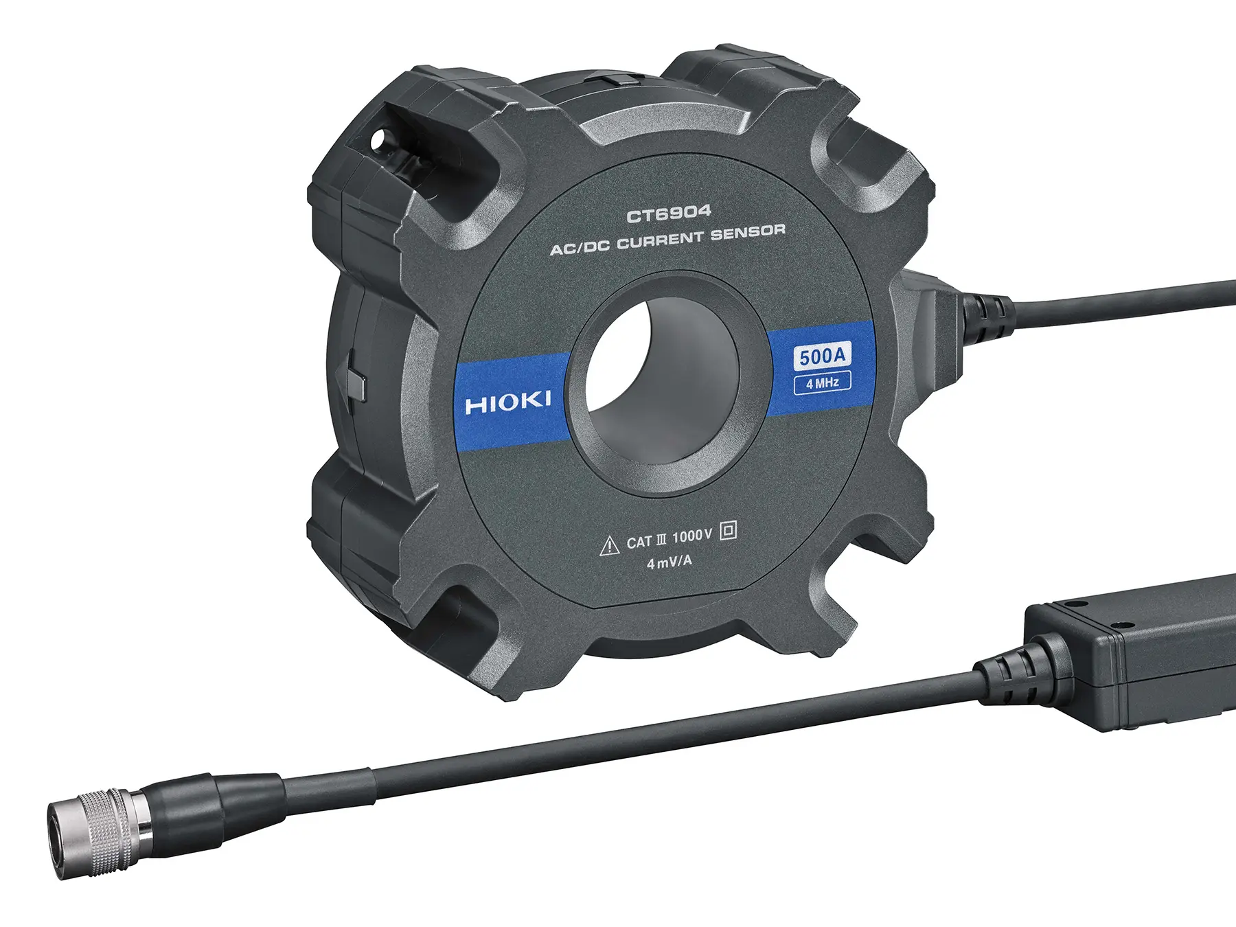
The VT1005 High Voltage Divider in combination with the PW8001 Power Analyzer and the CT6904A Current Sensor represents the optimum solution to measure loss of high voltage, high frequency inductors and transformers. With this set up accurate loss measurements can be guaranteed even at a frequency of 300 kHz due to the strong noise resistivity and phase accuracy at high frequencies.
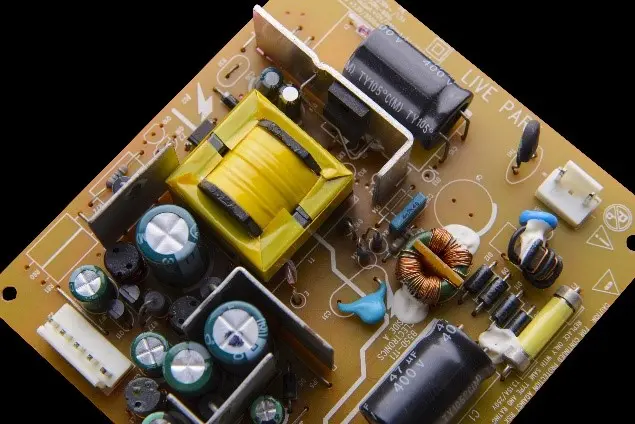
In the light of the increased use of SiC and GaN semiconductors, high frequency and high voltage applications are on the rise. These require highly accurate measurement solutions like the VT1005 with HIOKI power analyzers to prove even small efficiency gains.
PW8001
HIOKI PW8001 - Modular 8-channel High Precision Power Analyzer
High-precision power analyzer for advanced efficiency testing and accurate power measurement in motors, inverters and power electronics. HIOKI PW8001 available now.
CT6904A
HIOKI CT6904A - High-precision AC/DC current sensor, 500 A / 4 MHz
High-precision AC/DC current sensor with 500 A range and 4 MHz bandwidth for accurate waveform analysis in power electronics testing. HIOKI CT6904A available now.
VT1005
HIOKI VT1005 - High-Precision 5000 V AC/DC Voltage Divider for Advanced Power Analysis
High-precision 5000 V AC/DC voltage divider for advanced power analysis and high-voltage measurement applications. HIOKI VT1005 available from HIOKI Europe.

