Log in or Sign up
Exclusively for business customers in the EU, Norway, UK and Switzerland
Fast shipment from Germany
Go to homepage
Maintenance
  • Battery testers handheld
  • Clamp meters
  • Insulation resistance meters
  • Loggers & recorders
  • Multimeters
  • Power loggers
  • Power quality analyzers
  • Resistance meters handheld
  • Phase sequence testers
  • Earth resistance testers
  • Lux meters
R&D / Production
  • Battery testers
  • Current sensing
    • Signal analysis
    • Precision sensors
    • General sensors
  • Probes
  • Loggers & recorders
  • LCR meters / Impedance analyzers
  • Power measurement
  • Resistance meters
  • More
Accessories
  • Cases, bags & protectors
  • Test fixtures
  • Test leads & probe tips
  • Power supplies
  • Connection cables
  • More
SALE (- 20%)
Spare parts
Blog
Log in
or sign up
Overview Your profile Addresses Payment methods Orders
€0.00*
Need help?
Need help?
Do you have questions or require assistance?

Get in touch:

hioki@hioki.eu

Contact form

Show all categories Power Analysis for High-Frequency Applications
Back Show Power Analysis for High-Frequency Applications
  • Maintenance
  • R&D / Production
  • Accessories
  • SALE (- 20%)
  • Spare parts
  • Blog
  1. You are here:
  2. Home
  3. Footer
  4. Customer Service
  5. Blog
  6. Power Analysis for High-Frequency Applications
  1. Higher Frequencies – Smaller Inverters
  2. The Lower the Power Loss, the Higher the Energy Efficiency
  3. The Two-Coil loss measurement with a power analyzer
  4. Accurate coil loss measurement
  5. EVs Will Soon Be Charged Wirelessly
  6. The solution: Accurate Coil Loss Measurement in Seconds
  7. Beyond 10 kHz, conventional power analyzers measure inaccurately
  8. Unique: Automatic Phase Shift Correction minimizes errors
  9. The ideal route to maximum precision

Power Analysis for High-Frequency Applications

Roy Hali · 30.10.2024
Power Electronics · 7 min. reading duration

The increasing use of SiC and GaN semiconductors in power electronics lead to higher switching frequencies. As a result, smaller and lighter coils can be used in power converters. This also puts major challenge for measurement technology that you need to improve efficiency. Conventional power analyzers produce inconsistent and even incorrect measurement results when analyzing coil loss at the high switching frequencies. The key to easily obtain accurate and repeatable results is automatic phase shift correction. HIOKI makes this possible by perfectly synchronizing the power analyzer with our current sensors and high voltage dividers.

Power Analysis for High-Frequency Applications
Roy Hali
Senior Application Engineer, HIOKI Europe
Share post!

Higher Frequencies – Smaller Inverters

Increasingly higher switching frequencies are a general trend in many areas of electrical engineering. Solid-state transformers, for example, make our power grids more flexible and robust. They stabilize the grids when these are heavily loaded by the decentralized feed-in of renewable energy sources, or when electric cars are charged all at once in peak hours. These transformers, also known as “Solid State Transformers” (SST), are much smaller and lighter than conventional power transformers because they operate at frequencies above 10 kHz.

The Lower the Power Loss, the Higher the Energy Efficiency

Especially in electromobility, ultra-fast inverters based on SiC and GaN semiconductors have now taken on a leading role, since their high operating frequencies allow them to be built much smaller and lighter. They are essential for converting the 11 kW charging voltage from AC to DC for the battery, for converting to three-phase AC for the electric motor, or for stepping down to 12 V or 24 V for auxiliary circuits. Coils play a central role in all these conversions. Needless to say, the lower the power loss in all the coils used, the greater the overall energy efficiency – and in EVs, this directly translates into significantly longer driving ranges.
HIOKI Stromsensoren & Leistungsanalysator

The Two-Coil loss measurement with a power analyzer

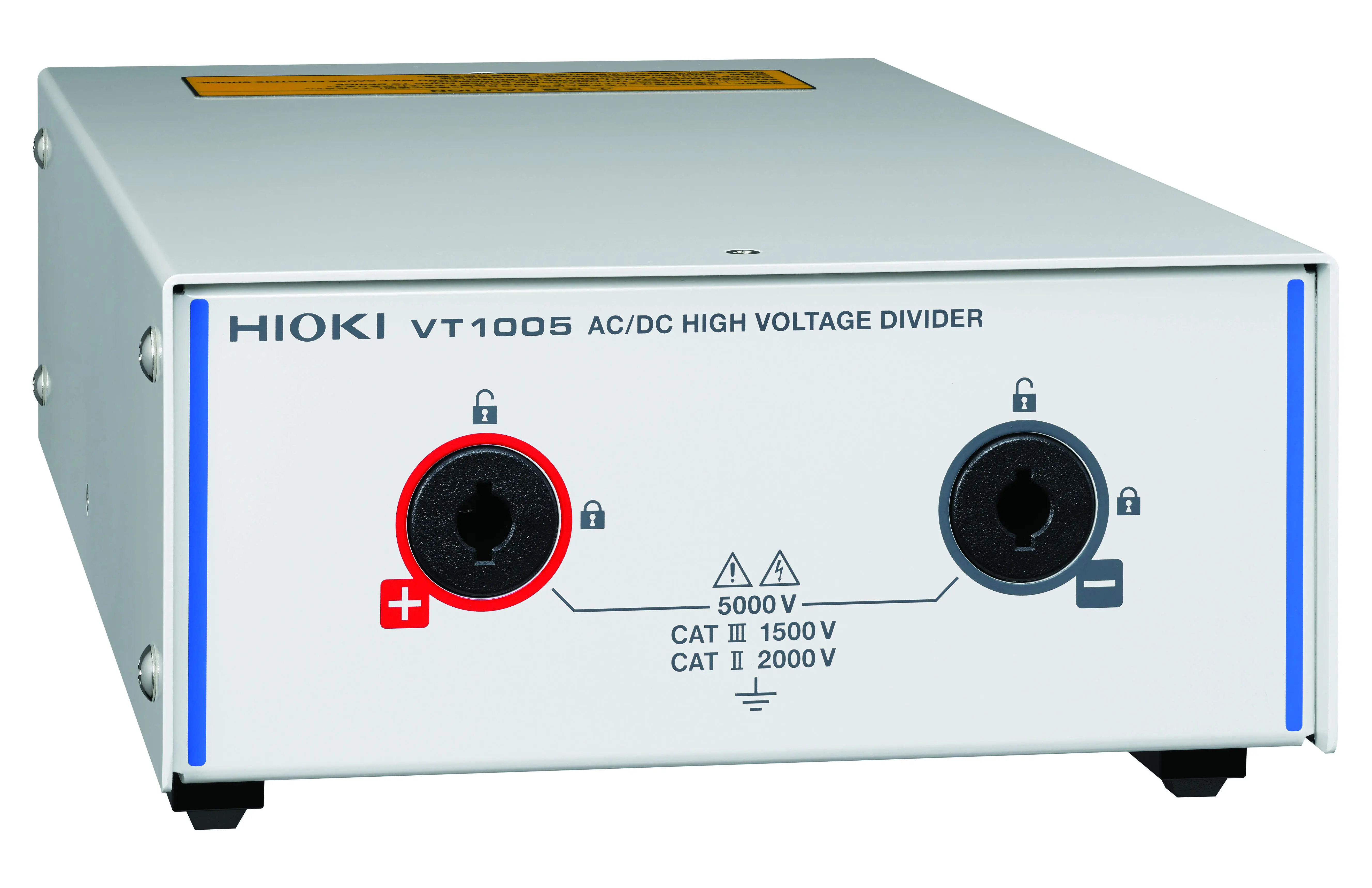
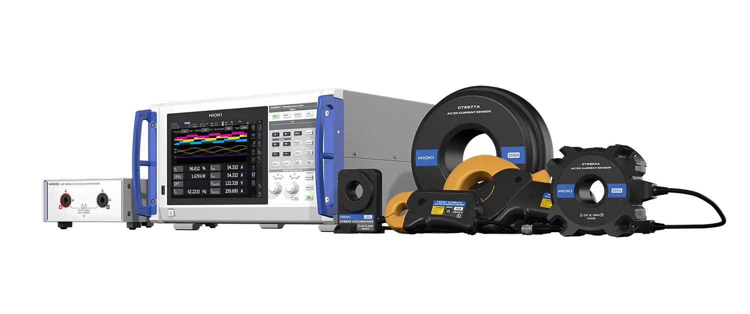
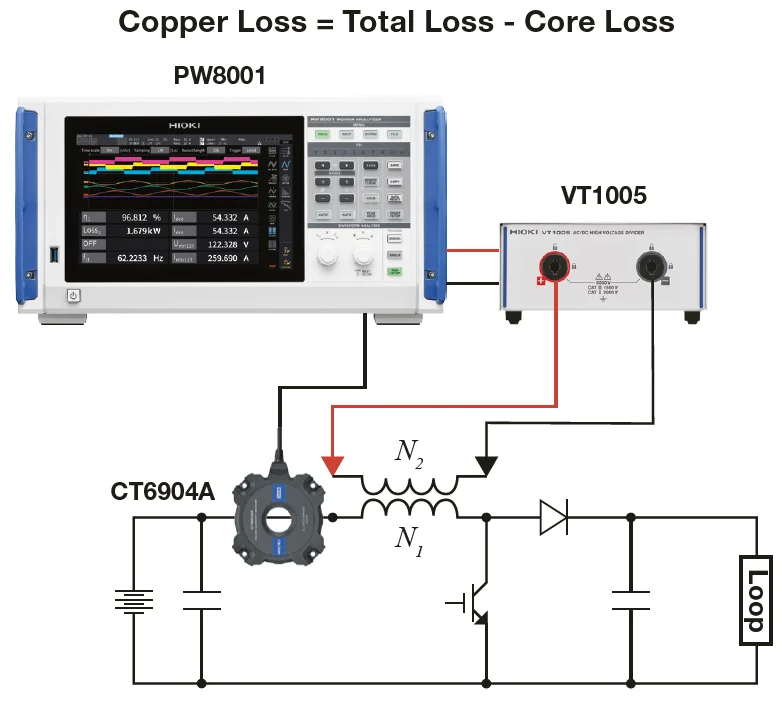
To determine the losses in coils, the so-called “Two-Coil Loss Measurement” is used. With this method, the total loss of the coil as well as the core loss or coil loss can be determined. In the primary coil (N1), both current and voltage are measured, while in the secondary coil (N2) only the voltage is measured. Figure 3 shows a simplified measurement setup using the PW8001 Power Analyzer together with a CT6904 current sensor and a VT1005 high-voltage divider. The measured values for voltages, current, phase angle, etc. form the basis for the calculation of the respective losses in the coils. These calculations are performed using the User Defined Calculation Functions (UDFs), which are provided by the user. The copper loss is calculated by subtracting the coil loss from the total loss.

Accurate coil loss measurement

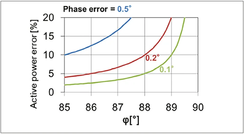
It is quite a challenge to accurately measure the loss of a coil accurately. To ensure useful results, it is recommended to measure the losses in actual working conditions, so for WPT this means at currents up to 500 A and a voltage at the receiving coil of 3 kV. The use of a high voltage divider is necessary to handle these high voltages. The power factor of the coils is extremely low. Due to this characteristic the influence of the phase error on the measurement result is extremely high, as is shown in figure 4 below.

EVs Will Soon Be Charged Wirelessly

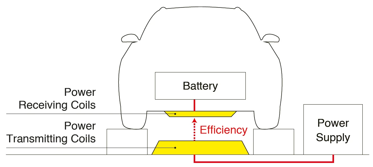
One important application of two-coil loss measurement is in wireless power transfer (WPT). Before long, the batteries of electric vehicles are expected to be charged wirelessly, just like electric toothbrushes or mobile phones via charging devices installed beneath parking spaces or even roadways.
Precise measurements of parameters such as voltage, current, power factor and harmonic distortion, enable engineers to better understand the performance of transmitting coils and receiving coils in a WPT system to ensure efficient and reliable energy transfer. Accurate, speedy assessment of input and output power as well as losses during contactless transmission increases the system performance and speeds up the development process.

The solution: Accurate Coil Loss Measurement in Seconds

To date, the focus of development engineers in the design of WPT has been on minimizing the switching and conduction losses of the semiconductors in the system. To increase system efficiency even further, it is also important to use the optimal coils in the system. It is therefore important to analyze the coil losses under operating conditions. A commonly used method to measure coil losses is the Calorimeter. This method is accurate, but it has one major disadvantage: the test can take up to half an hour.
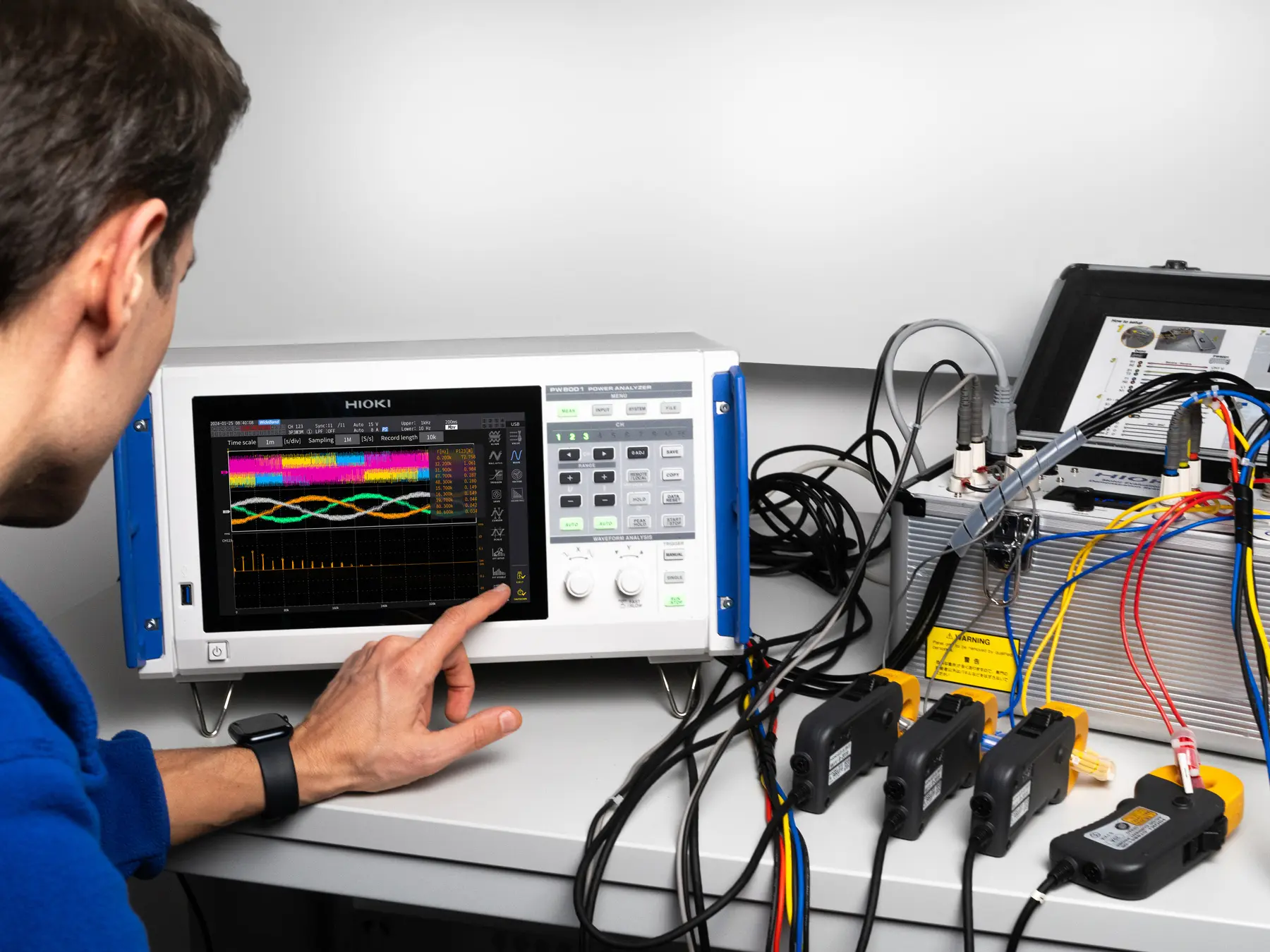
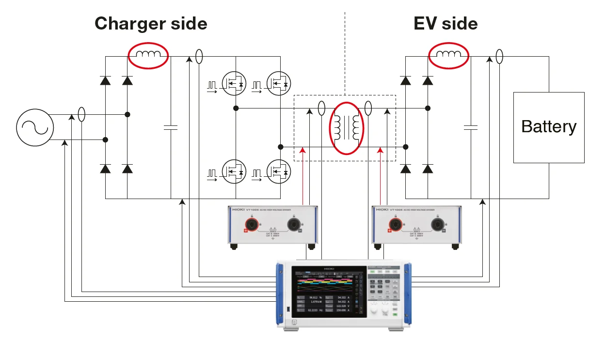
Alternatively, a power analyzer can be used to determine coil losses in just seconds. But this is easier said than done, as it is a challenging measurement. Below is the basic electrical diagram of an EV WPT system shown with the system coils circled in red (figure 6). Using the PW8001 Power Analyzer combined with HIOKI current sensors and voltage dividers, overall system efficiency and coil losses can be accurately determined thanks to several unique features.

Beyond 10 kHz, conventional power analyzers measure inaccurately

The test results of traditional power analyzers with an internal shunt resistor, become unreliable for coil loss measurement beyond the 10 kHz threshold. Phase errors have a minimal impact up to switching frequencies of approximately 10 kHz. However, beyond this threshold, many power analyzers yield inaccurate loss results due to inaccurate determination of the phase angle between the voltage and the current. For higher current measurements, they also utilize third-party current sensors that were never specifically designed for coil loss measurement, adding to the poor accuracy and repeatability.
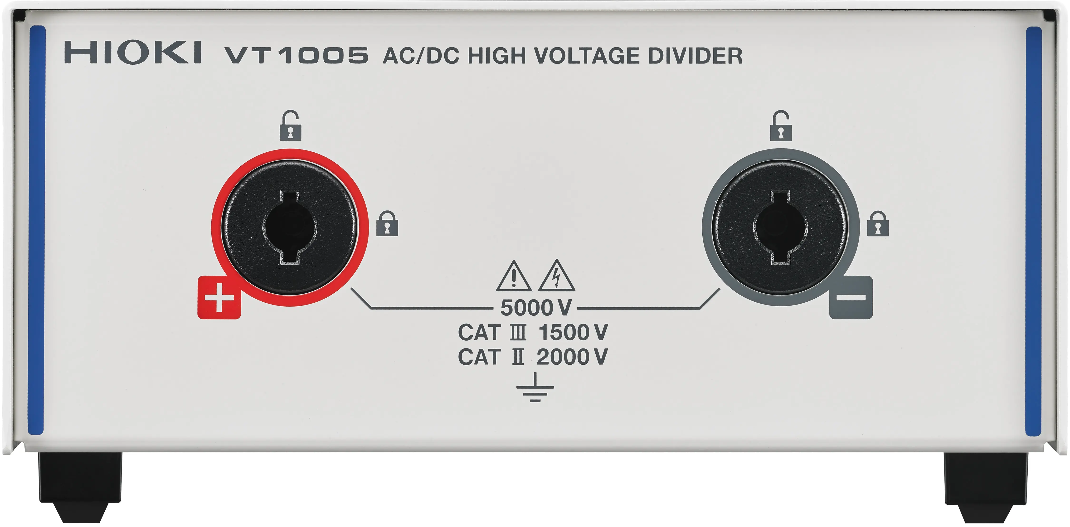
To overcome this challenge at high frequencies, the PW8001 Power Analyzer compensates for the known phase error of HIOKI current sensors and of the VT1005 voltage divider (see Fig. 6). For current sensors, this phase error compensation is even performed automatically by the PW8001 when used together with the matching HIOKI sensors—this unique function is what we call Automatic Phase Shift Correction.

Unique: Automatic Phase Shift Correction minimizes errors

To correct measurement errors in the phase difference at high switching frequencies, HIOKI has developed a particularly effective phase shift correction for the PW8001 power analyzer. Two conditions need to be met for this to function reliably:
  • a power analyzer that performs phase correction correctly,
  • a zero-flux current sensor with a known time delay.
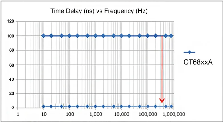
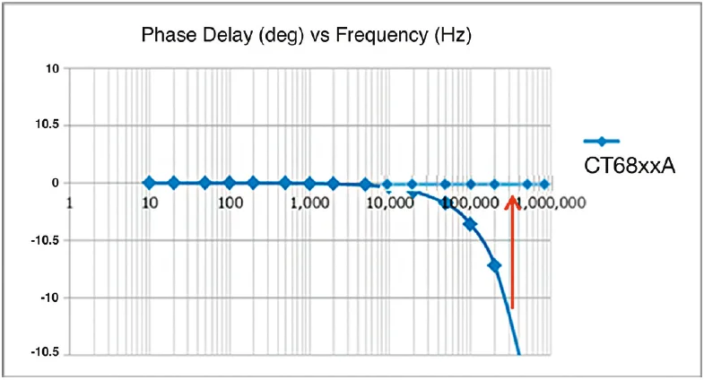
The phase shift correction is comparable to the familiar deskew function in oscilloscopes: if two different signals arrive at the oscilloscope with a time shift due to latency, the deskew function eliminates the signal offset by compensating for the latency with a fixed time value. The phase error is directly related to the time delay of the current sensor. For a current sensor of the CT68xxA series from HIOKI, for example, the delay is shown in Figure 8. You can see the time delay in nanoseconds depending on the frequency.
Important to know: A delay of 100 ns at 100 Hz does not have the same effect as a delay of 100 ns at 1 MHz. This becomes clear when the time delay is converted into the phase delay (expressed in degrees) in figure 9.

The ideal route to maximum precision

HIOKI has developed its zero-flux current sensors together with its Power Analyzers for a good reason: It’s the solution to precision and reliability. In order to efficiently compensate for phase delay, the time delay of the current sensor must remain constant regardless of the frequency. In addition, the most important key figures of the current sensors are automatically transmitted to the Power Analyzer as soon as current sensor is connected and the phase error of the current sensor is automatically compensated. And there you have it: Coil loss measurement. Accurate. In seconds.
PW8001 - Modular 8-channel High Precision Power Analyzer PW8001 - Modular 8-channel High Precision Power Analyzer
PW8001
PW8001 - Modular 8-channel High Precision Power Analyzer
High-precision power analyzer for analysing the efficiency of inverters and inverters with basic accuracy of ±0.03%, sampling rate of 15 MHz, 18-bit AD converters, automatic phase shift correction, data update rate of 1 ms.
View product
CT6875A - AC/DC Current sensor, 500 A / 2 MHz CT6875A - AC/DC Current sensor, 500 A / 2 MHz
CT6875A
CT6875A - AC/DC Current sensor, 500 A / 2 MHz
The CT6875 AC/DC Current Sensor is designed for accurate current measurements across a broad frequency range, from DC to 2 MHz (Model CT6875-01: DC to 1.5 MHz). With a rated current of 500 A, it is ideal for R&D, quality evaluation, manufacturing, and maintenance in industries such as wireless charging systems, inverter motors, PV power conditioners, and EV quick charging facilities. In combination with the Power Analyzer PW8001, the sensor allows for precise high-frequency and low power factor measurements. Technical Details: Rated Current: 500 A Frequency Bandwidth: CT6875: DC to 2 MHzBasic Accuracy: Amplitude: ±0.04 % rdg. ±0.008 % f.s., Phase: ±0.08° Maximum Conductor Diameter: 36 mm Maximum Rated Voltage to Ground: 1000 V CAT III Operating Temperature: -40°C to 85°C Input Impedance Requirement: 1 MΩ or higher Output Terminal: ME15W Cable length: 3mMore than specs – find more details here:🔗 Measure Power with Precision – Across All Applications

€1,698.00*
View product
CT6845A - AC/DC Current Clamp, Fluxgate, 500 A / 200 kHz CT6845A - AC/DC Current Clamp, Fluxgate, 500 A / 200 kHz
CT6845A
CT6845A - AC/DC Current Clamp, Fluxgate, 500 A / 200 kHz
AC/DC current clamp using advanced fluxgate technology, 500A rated current, basic accuracy ±0.2% rdg., wide temperature range of -40 °C to 85 °C, bandwidth from DC to 200 kHz, maximum conductor diameter 50 mm, cable length 3 m

€1,988.00*
View product
CT6876A - AC/DC Current sensor, 1000A / 1.5 MHz CT6876A - AC/DC Current sensor, 1000A / 1.5 MHz
CT6876A
CT6876A - AC/DC Current sensor, 1000A / 1.5 MHz
Product Description for CT6876 AC/DC Current Sensor The CT6876 AC/DC Current Sensor is designed for accurate current measurements with a broad frequency range from DC to 1.5 MHz. With a rated current of 1000 A, it is ideal for demanding applications in industries such as inverter motors, electric vehicles, and power electronics.The sensor offers excellent noise resistance and high precision, making it a top choice for high-current, high-speed measurements. When combined with Hioki's Power Analyzers, it ensures accurate power conversion efficiency measurements, especially in high-frequency environments. Technical Details: Model: CT6876 Rated Current: 1000 A Frequency Bandwidth: DC to 1.5 MHzBasic Accuracy: Amplitude: ±0.04% rdg. ±0.008% f.s. Phase: ±0.1° Maximum Conductor Diameter: 36 mm Maximum Rated Voltage to Ground: 1000 V CAT III Operating Temperature: -40°C to 85°CInput Impedance Requirement: 1 MΩ or higher Output Terminal: ME15W

€2,268.00*
View product
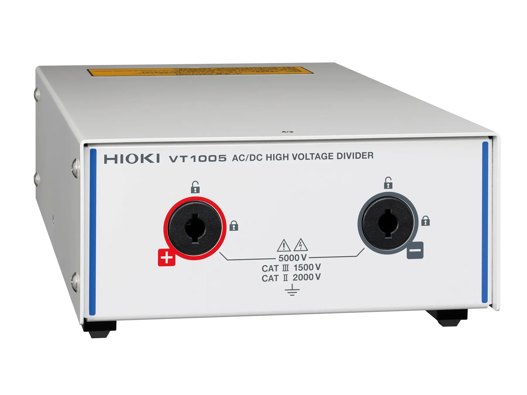
VT1005 - High-Precision 5000 V AC/DC Voltage Divider for Advanced Power Analysis VT1005 - High-Precision 5000 V AC/DC Voltage Divider for Advanced Power Analysis
VT1005
VT1005 - High-Precision 5000 V AC/DC Voltage Divider for Advanced Power Analysis
AC/DC high-voltage divider up to 5 kVrms, bandwidth DC to 4 MHz (–3 dB), 1000:1 division ratio, ±0.08% DC accuracy, ±0.04% accuracy at 50/60 Hz, amplitude flatness ±0.1% to 200 kHz, phase flatness ±0.1° to 500 kHz, CMRR 80 dB at 100 kHz, BNC output
View product
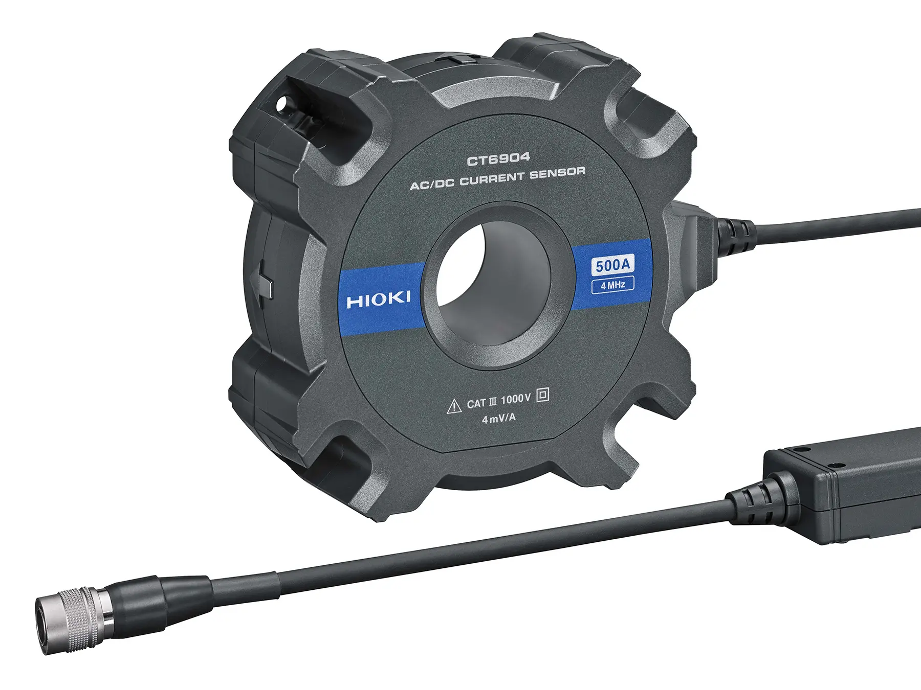
CT6904A - High-precision AC/DC current sensor, 500 A / 4 MHz CT6904A - High-precision AC/DC current sensor, 500 A / 4 MHz
CT6904A
CT6904A - High-precision AC/DC current sensor, 500 A / 4 MHz
High-accuracy pass-through AC/DC current sensor with zero-flux fluxgate, up to 500 A, DC–4 MHz bandwidth, 120 dB CMRR at 100 kHz, ±5 ppm linearity, flat frequency response, 3 m cable with ME15W connector.
View product
Follow us
Measuring instruments & Accessories
  • Maintenance
  • R&D / Production
  • Accessories
  • SALE (- 20%)
  • Spare parts
Measurement solutions & tips
  • • Zero-Flux Current Clamps: from mA to kA​
  • • Wideband Current Sensors up to 500A & 120 MHz
  • • MR6000-MAX Memory Recorder Bundle​
  • • The Most Versatile Multi-Channel Data Logger​
  • • Precision Current Data Logging. Ultra-compact.
  • • Measure Power with Precision – Across All Applications
Blog Articles
  • • DC Current Measurement and Bandwidth​
  • • Zero-Flux Current Sensors: Like in “Back to the Future”?
  • • Your Path to Better Energy Efficiency: Current Mapping​
  • • Never Miss a Beat: Choosing the Right Sampling Rate for Data Acquisition​
  • • A dedicated resistance meter? Here is when it makes sense…​
Customer Service
  • About Us
  • Shipping & Returns
  • Where else to buy
  • Contact
  • Downloads
Legal
  • Imprint
  • Terms & Conditions
  • Data protection
  • Battery disposal
  • Cookie settings
Payment methods
Credit Card (via Stripe)
Advance Payment
PayPal
Klarna (via Stripe)
© 2025 HIOKI EUROPE GmbH

* All prices excl. VAT plus shipping costs