Log in or Sign up
Exclusively for business customers in the EU, Norway, UK and Switzerland
Fast shipment from Germany
Go to homepage
Maintenance
  • Battery testers handheld
  • Clamp meters
  • Insulation resistance meters
  • Loggers & recorders
  • Multimeters
  • Power loggers
  • Power quality analyzers
  • Resistance meters handheld
  • Phase sequence testers
  • Earth resistance testers
  • Lux meters
R&D / Production
  • Battery testers
  • Current sensing
    • Signal analysis
    • Precision sensors
    • General sensors
  • Probes
  • Loggers & recorders
  • LCR meters / Impedance analyzers
  • Power measurement
  • Resistance meters
  • More
Accessories
  • Cases, bags & protectors
  • Test fixtures
  • Test leads & probe tips
  • Power supplies
  • Connection cables
  • More
SALE (- 20%)
Spare parts
Blog
Log in
or sign up
Overview Your profile Addresses Payment methods Orders
€0.00*
Need help?
Need help?
Do you have questions or require assistance?

Get in touch:

hioki@hioki.eu

Contact form

Show all categories Derating of Current Sensors: What is it and why?
Back Show Derating of Current Sensors: What is it and why?
  • Maintenance
  • R&D / Production
  • Accessories
  • SALE (- 20%)
  • Spare parts
  • Blog
  1. You are here:
  2. Home
  3. Footer
  4. Customer Service
  5. Blog
  6. Derating of Current Sensors: What is it and why?
  1. What is the reason for the derating of maximum input currents?
  2. When does derating actually matter?
  3. Switching frequencies are getting higher - what about the sensors?

Derating of Current Sensors: What is it and why?

Kai Scharrmann · 31.10.2025
Power Electronics | currrent sensor | Current Measurement | Derating · 6 min. reading duration

In an article about DC current measurement and bandwidth I wrote that "the derating of a current sensor and the sensor's bandwidth have nothing to do with each other".
Derating of Current Sensors: What is it and why?
Kai Scharrmann
VP Sales, PM & Marketing, HIOKI Europe
Share post!
The bandwidth of a current sensor defines how quickly the sensor can detect and respond to changes in the measured current. Like with an oscilloscope, the bandwidth of a current sensor also defines at which current the output signal of the sensor is -3dB lower than the input current signal.

The derating of a current sensor describes which input current a current sensor can handle at which frequency.
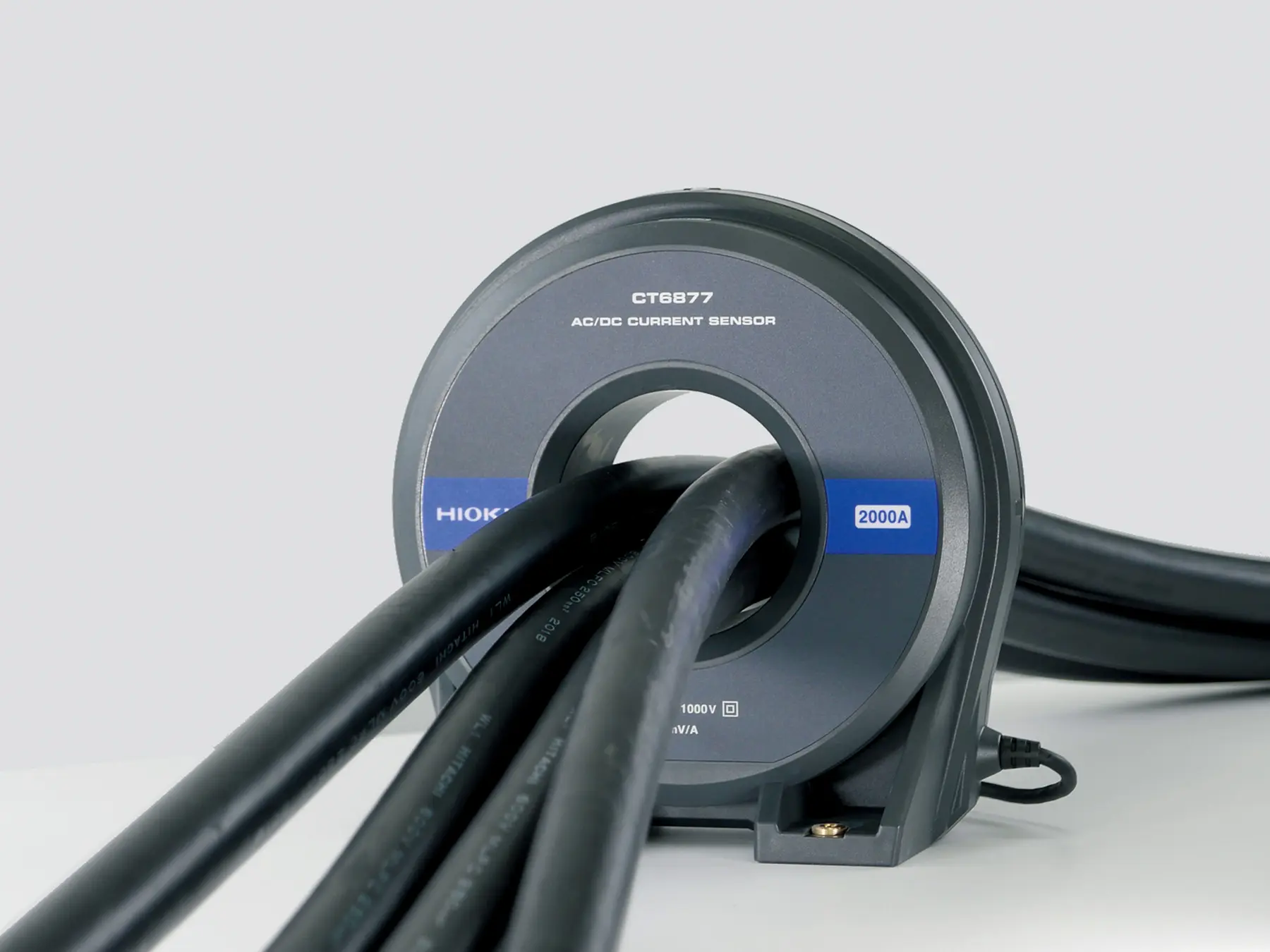
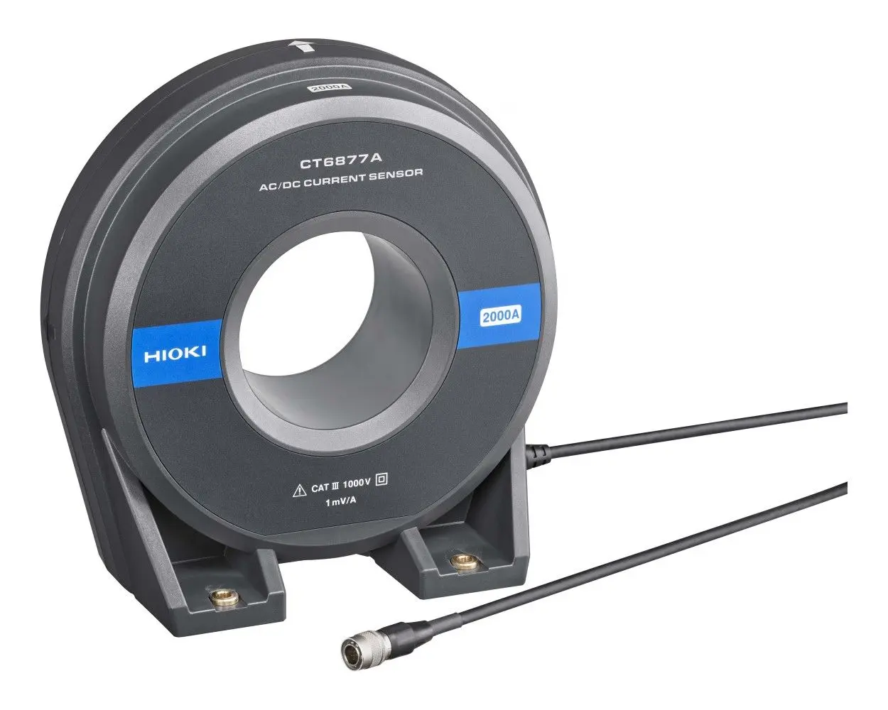
HIOKI's CT6877A zero-flux current sensor
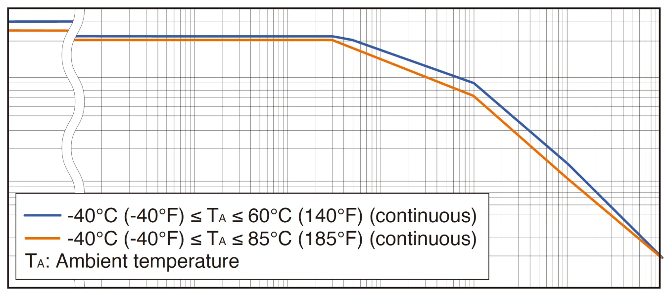
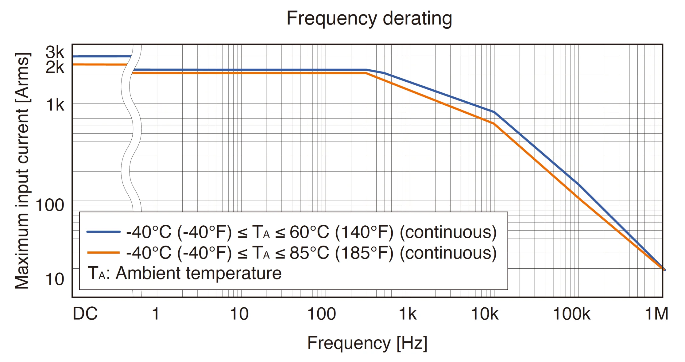
Let's look at the frequency derating curve of HIOKI's CT6877A zero-flux current sensor. The banner specs of this sensor state a maximum input current of 2000A and a bandwidth of 1MHz. The current is specified for continous use at a maximum temperature of 85°C (orange line). As you can see from the blue line, the maximum current is higher when used in an environment with a lower temperature.
Frequency derating of HIOKI's CT6877A zero-flux current sensor
Following both the blue and the orange line, the maximum input current of the sensor is flat until 300Hz, at which point it starts to drop. At 10kHz the maximum input current has dropped to 600A, and at 1MHz the maximum input current is just 10A.

What is the reason for the derating of maximum input currents?


You can get a very good indication why derating is necessary from the above derating curve: The current represented by the blue line, which shows the derating for a maximum ambient temperature of 65°C, is higher than the current represented by the orange line, which shows the derating for a maximum ambient temperature of 85°C. That's because heat is the main reason for derating.
The ambient temperature, of course, only plays a minor role. More relevant causes are heat generation on the circuit and heat generation caused by higher frequency eddy currents.

When does derating actually matter?


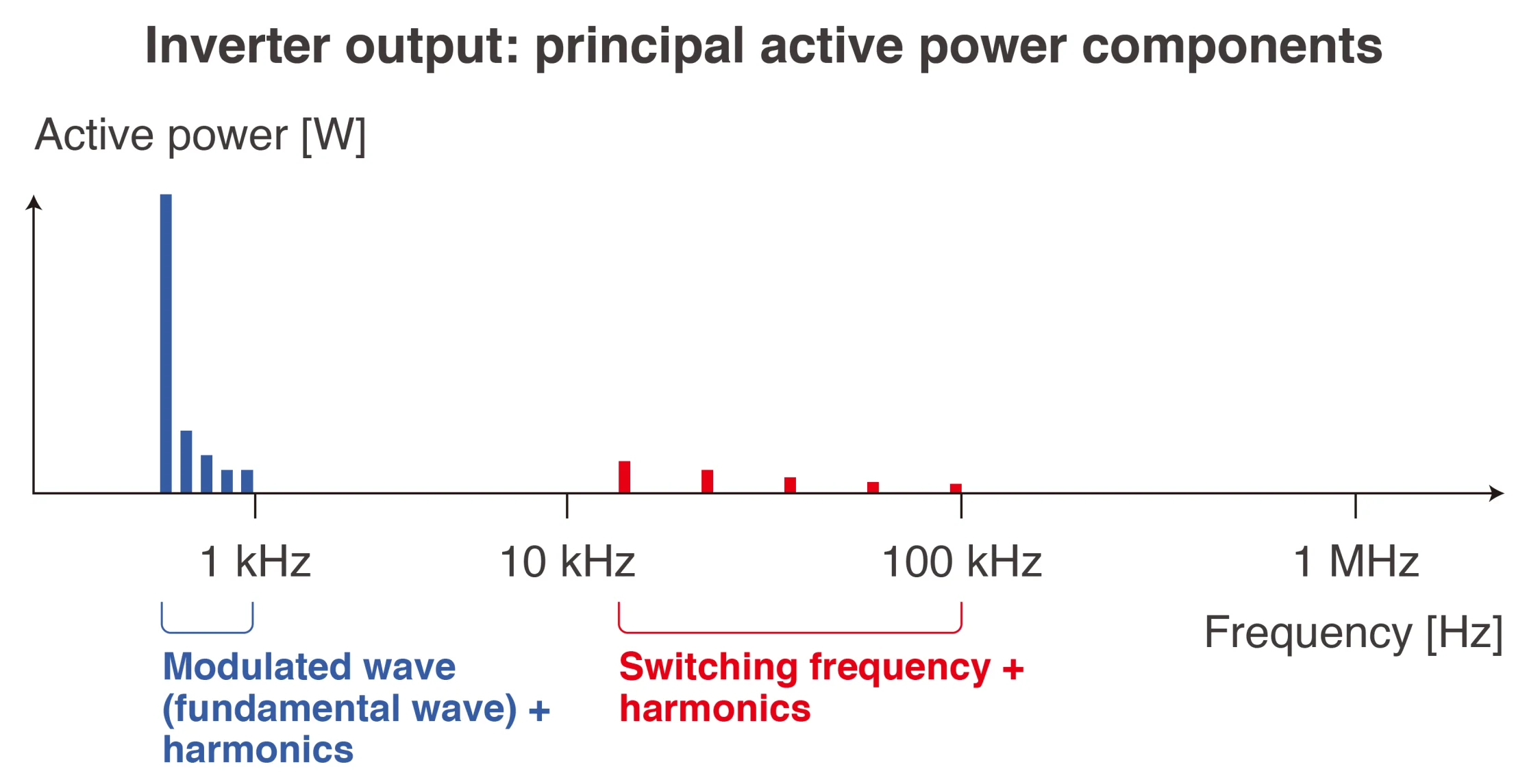
If you measure 50Hz AC currents with a couple of harmonics or even DC currents from a battery, then derating might not be a huge concern for you. The story is different if, for example, you need to measure currents of an inverter output.
Active power of an inverter
The above image shows the active power of an inverter output over a wide frequency band. As you can see, the highest amount of power and therefore also currents are in a frequency range where current derating typically hasn't started yet. Especially for power analysis it is absolutely crucial to also precisely measure currents in the range of the switching frequency of an inverter.

Of course, these currents are much lower than the currents of the modulated wave and it's harmonics, but with the developments of new inverter technologies like SiC and GaN it is crucial to ensure that the derating of current sensors allows to measure these currents.

Switching frequencies are getting higher - what about the sensors?

The derating requirements for a current sensor which was launched ten years ago were not the same as for a current sensor which was launched recently.
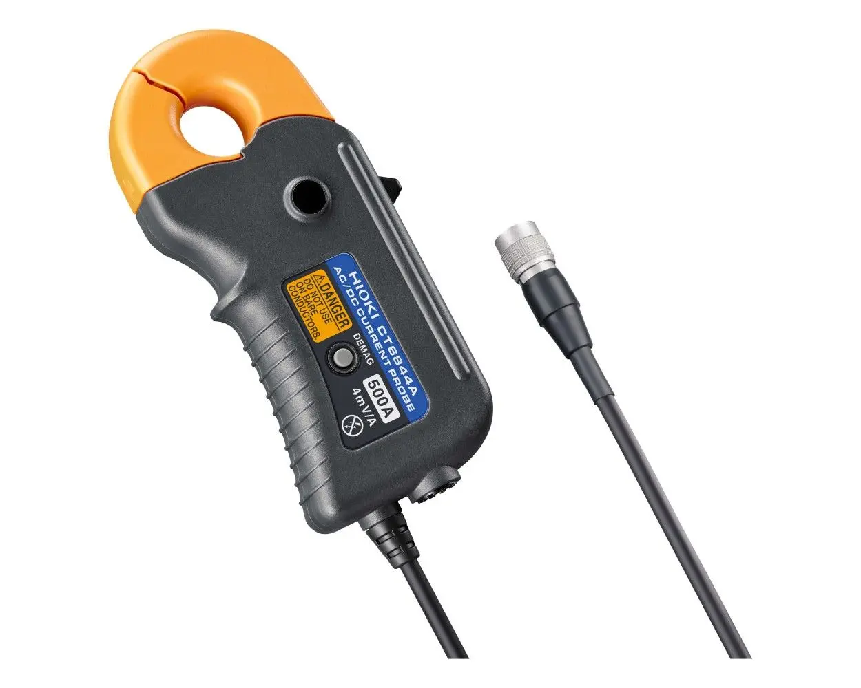
HIOKI CT6844A zero-flux current probe
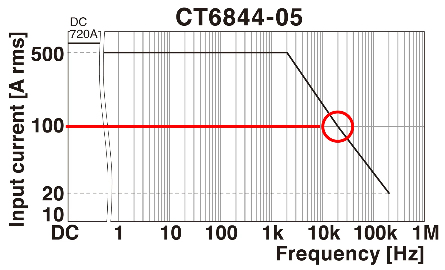
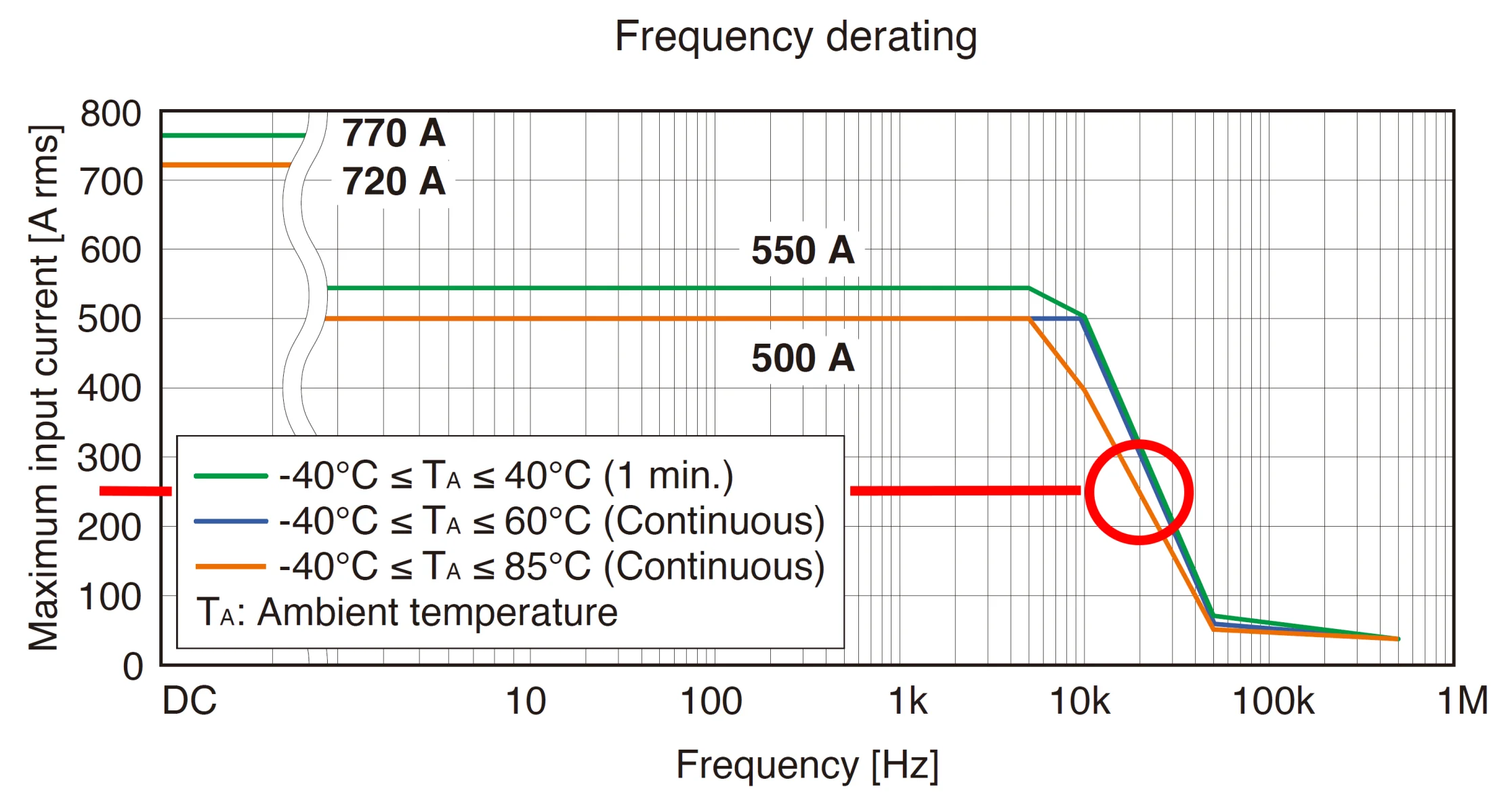
The CT6844A is a current probe with a maximum input current of 500A. The predecessor of this sensor was called CT6844-05 with the same maximum input current of 500A. The maximum input current at 20kHz of the older CT6844-05 is 100A.
Derating of CT6844-05 current probe
That is still an impressive number - especially given the fact that this is a current clamp with a split magnetic core and not a push-through sensor. The CT6844A, however, has a maximum input current at 20kHz of around 250A.
Derating of CT6844A current probe
As a conclusion, derating describes the maximum input current of a current sensor over it's bandwidth. The derating curve of the sensor helps users to ensure that the higher frequency currents they measure can be handled by the current sensor.

The current sensors used as example in this article are based on zero-flux technology. Find out in this article where the name "zero flux" actually comes from.
CT6877A - AC/DC-Current sensor, 2000 A / 1 MHz CT6877A - AC/DC-Current sensor, 2000 A / 1 MHz
CT6877A
CT6877A - AC/DC-Current sensor, 2000 A / 1 MHz
Hioki's pass-through AC/DC current sensors are premium devices for use with power meters, memory HiCorders and high performance oscilloscopes.
View product
20 %
CT6844A - AC/DC High-accuracy Current Clamp, 500 A / 500 kHz CT6844A - AC/DC High-accuracy Current Clamp, 500 A / 500 kHz
CT6844A
CT6844A - AC/DC High-accuracy Current Clamp, 500 A / 500 kHz
AC/DC current clamp using advanced fluxgate technology, 500A rated current, basic accuracy ±0.2% rdg., wide temperature range of -40 °C to 85 °C, wide bandwidth from DC to 500 kHz, maximum conductor diameter 20 mm, cable length 3 m

€1,590.40* €1,988.00*
View product
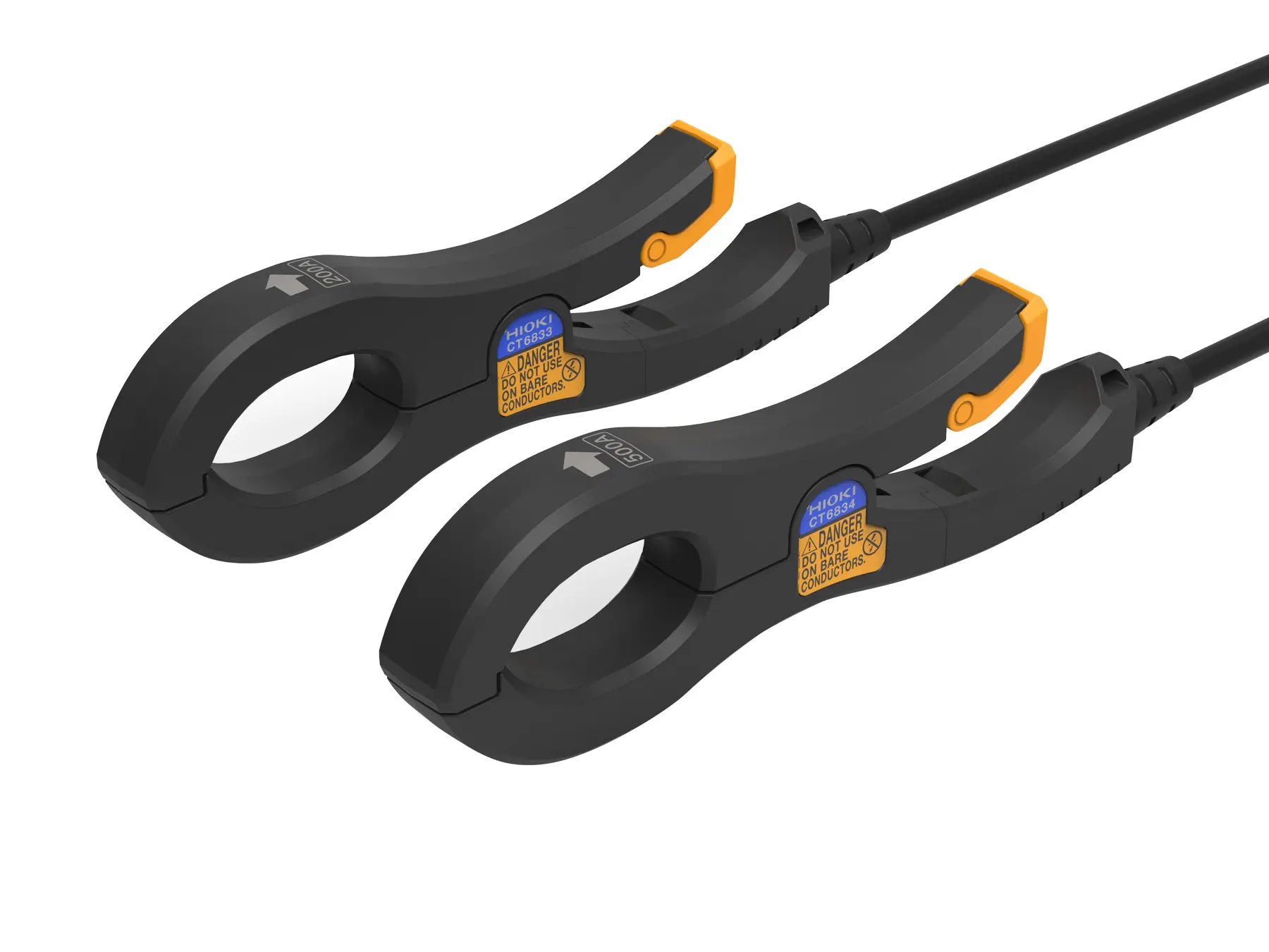
CT6833 - Super-slim AC/DC high-accuracy Current Clamp, 200 A / 50 kHz CT6833 - Super-slim AC/DC high-accuracy Current Clamp, 200 A / 50 kHz
CT6833
CT6833 - Super-slim AC/DC high-accuracy Current Clamp, 200 A / 50 kHz
Ultra-slim AC/DC current clamp using advanced fluxgate technology, 200 A rated current, DC to 50 kHz frequency bandwidth, high accuracy ±0.07% rdg., wide temperature range of -40°C to +85°C, maximum conductor diameter 20 mm, cable length 5 m

€2,178.00*
View product
CT6834 - Super-slim AC/DC high-accuracy Current Clamp, 500 A / 50 kHz HIOKI CT6834 current clamp low phaseshift
CT6834
CT6834 - Super-slim AC/DC high-accuracy Current Clamp, 500 A / 50 kHz
Ultra-slim AC/DC current clamp using advanced fluxgate technology, 500 A rated current, DC to 50 kHz frequency bandwidth, high accuracy ±0.07% rdg., wide temperature range of -40°C to +85°C, maximum conductor diameter 20 mm, cable length 5 m

€2,248.00*
View product
CT6845A - AC/DC Current Clamp, Fluxgate, 500 A / 200 kHz CT6845A - AC/DC Current Clamp, Fluxgate, 500 A / 200 kHz
CT6845A
CT6845A - AC/DC Current Clamp, Fluxgate, 500 A / 200 kHz
AC/DC current clamp using advanced fluxgate technology, 500A rated current, basic accuracy ±0.2% rdg., wide temperature range of -40 °C to 85 °C, bandwidth from DC to 200 kHz, maximum conductor diameter 50 mm, cable length 3 m

€1,988.00*
View product
CT6841A - AC/DC High-accuracy Current Clamp, 20 A / 2 MHz CT6841A - AC/DC High-accuracy Current Clamp, 20 A / 2 MHz
CT6841A
CT6841A - AC/DC High-accuracy Current Clamp, 20 A / 2 MHz
AC/DC current clamp using advanced fluxgate technology, 20A rated current, basic accuracy ±0.2% rdg., wide temperature range of -40 °C to 85 °C, wide bandwidth from DC to 2 MHz, maximum conductor diameter 20 mm, cable length 3 m

€1,818.00*
View product
CT6846A - AC/DC High-accuracy Current Clamp, 1000 A / 100 kHz CT6846A - AC/DC High-accuracy Current Clamp, 1000 A / 100 kHz
CT6846A
CT6846A - AC/DC High-accuracy Current Clamp, 1000 A / 100 kHz
AC/DC current clamp using advanced fluxgate technology, 1000A rated current, basic accuracy ±0.2% rdg., wide temperature range of -40 °C to 85 °C, bandwidth from DC to 100 kHz, maximum conductor diameter 50 mm, cable length 3 m

€2,328.00*
View product
CT6843A - AC/DC High-accuracy Current Clamp, 200 A / 700 kHz CT6843A - AC/DC High-accuracy Current Clamp, 200 A / 700 kHz
CT6843A
CT6843A - AC/DC High-accuracy Current Clamp, 200 A / 700 kHz
AC/DC current clamp using advanced fluxgate technology, 200A rated current, basic accuracy ±0.2% rdg., wide temperature range of -40 °C to 85 °C, wide bandwidth from DC to 700 kHz, maximum conductor diameter 20 mm, cable length 3 m

€1,878.00*
View product
CT6875A - AC/DC Current sensor, 500 A / 2 MHz CT6875A - AC/DC Current sensor, 500 A / 2 MHz
CT6875A
CT6875A - AC/DC Current sensor, 500 A / 2 MHz
The CT6875 AC/DC Current Sensor is designed for accurate current measurements across a broad frequency range, from DC to 2 MHz (Model CT6875-01: DC to 1.5 MHz). With a rated current of 500 A, it is ideal for R&D, quality evaluation, manufacturing, and maintenance in industries such as wireless charging systems, inverter motors, PV power conditioners, and EV quick charging facilities. In combination with the Power Analyzer PW8001, the sensor allows for precise high-frequency and low power factor measurements. Technical Details: Rated Current: 500 A Frequency Bandwidth: CT6875: DC to 2 MHzBasic Accuracy: Amplitude: ±0.04 % rdg. ±0.008 % f.s., Phase: ±0.08° Maximum Conductor Diameter: 36 mm Maximum Rated Voltage to Ground: 1000 V CAT III Operating Temperature: -40°C to 85°C Input Impedance Requirement: 1 MΩ or higher Output Terminal: ME15W Cable length: 3mMore than specs – find more details here:🔗 Measure Power with Precision – Across All Applications

€1,698.00*
View product
CT6876A - AC/DC Current sensor, 1000A / 1.5 MHz CT6876A - AC/DC Current sensor, 1000A / 1.5 MHz
CT6876A
CT6876A - AC/DC Current sensor, 1000A / 1.5 MHz
Product Description for CT6876 AC/DC Current Sensor The CT6876 AC/DC Current Sensor is designed for accurate current measurements with a broad frequency range from DC to 1.5 MHz. With a rated current of 1000 A, it is ideal for demanding applications in industries such as inverter motors, electric vehicles, and power electronics.The sensor offers excellent noise resistance and high precision, making it a top choice for high-current, high-speed measurements. When combined with Hioki's Power Analyzers, it ensures accurate power conversion efficiency measurements, especially in high-frequency environments. Technical Details: Model: CT6876 Rated Current: 1000 A Frequency Bandwidth: DC to 1.5 MHzBasic Accuracy: Amplitude: ±0.04% rdg. ±0.008% f.s. Phase: ±0.1° Maximum Conductor Diameter: 36 mm Maximum Rated Voltage to Ground: 1000 V CAT III Operating Temperature: -40°C to 85°CInput Impedance Requirement: 1 MΩ or higher Output Terminal: ME15W

€2,268.00*
View product
Newsletter
Subscribe to the free newsletter and do not miss any news or promotions.
Privacy Policy / Terms and Conditions*
Follow us
Measuring instruments & Accessories
  • Maintenance
  • R&D / Production
  • Accessories
  • SALE (- 20%)
  • Spare parts
Measurement solutions & tips
  • • Zero-Flux Current Clamps: from mA to kA​
  • • Wideband Current Sensors up to 500A & 120 MHz
  • • MR6000-MAX Memory Recorder Bundle​
  • • The Most Versatile Multi-Channel Data Logger​
  • • Precision Current Data Logging. Ultra-compact.
  • • Measure Power with Precision – Across All Applications
Blog Articles
  • • DC Current Measurement and Bandwidth​
  • • Zero-Flux Current Sensors: Like in “Back to the Future”?
  • • Your Path to Better Energy Efficiency: Current Mapping​
  • • Never Miss a Beat: Choosing the Right Sampling Rate for Data Acquisition​
  • • A dedicated resistance meter? Here is when it makes sense…​
Customer Service
  • About Us
  • Shipping & Returns
  • Where else to buy
  • Contact
  • Downloads
Legal
  • Imprint
  • Terms & Conditions
  • Data protection
  • Battery disposal
  • Cookie settings
Payment methods
Credit Card (via Stripe)
Advance Payment
PayPal
Klarna (via Stripe)
© 2025 HIOKI EUROPE GmbH

* All prices excl. VAT plus shipping costs