Simplify Testing with Integrated Recording and Simulation
Testing modern electronic systems goes far beyond simple data recording. Engineers must reliably replicate real-world conditions, generate custom test signals, and simulate edge-case scenarios to validate system performance in ECU testing, embedded systems, and power electronics workflows.
Data recorders equipped with signal generator modules can both capture data and generate signals. The integration of these functions enables a seamless transition between measurement and simulation, supporting a wide range of test scenarios with a single instrument.
This article presents three practical applications of this dual functionality:
- Reproduction of Recorded Waveforms – enables precise validation by recreating real events in the laboratory.
- Creation of Custom Signal Waveforms – for simulating edge cases and designing tests that go beyond recorded data.
- Injection of Anomalies – for simulating faults and disturbances to test systems under extreme conditions.
1. Recreate Real Conditions: Reproduce Measured Signals
One of the most useful applications of combined recording and signal generation is the ability to replay a signal captured during testing — without the need for additional equipment.
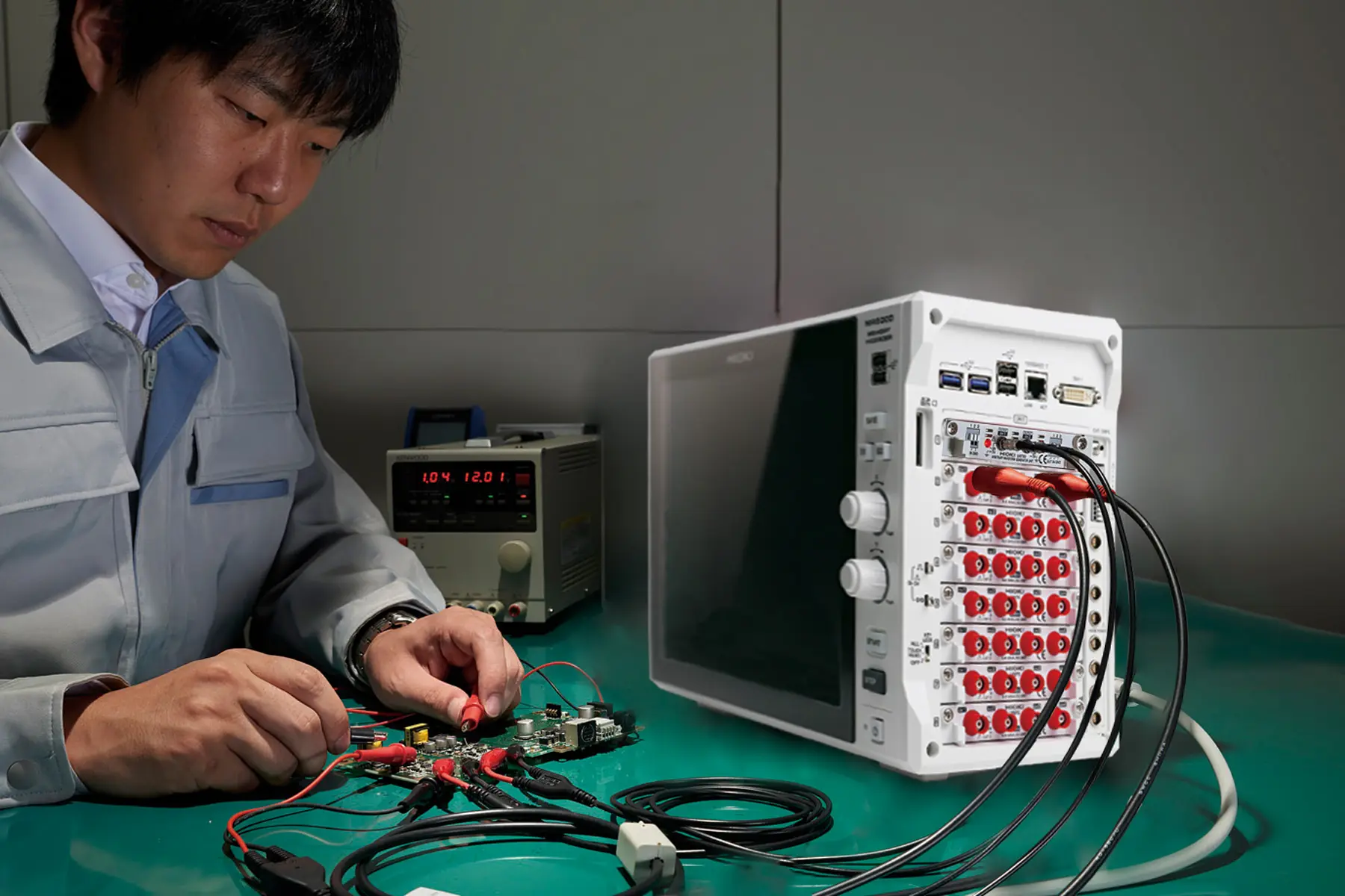
For example, a team validating a suspension control system can record vehicle signals during a test drive and later reproduce these conditions in the lab to drive an actuator or another device under test (DUT). This makes it possible to replicate specific dynamic events under controlled and repeatable conditions — essential for troubleshooting, stress testing, or validating known fault scenarios.
Since the same platform handles both recording and signal generation, there is no need for extra equipment such as separate DAQ systems, (arbitrary) signal generators, or converters. The result: simplified test setups, faster transitions between test phases, and more consistent results across multiple test cycles.
2. Freely Design Signals through Precise Simulation
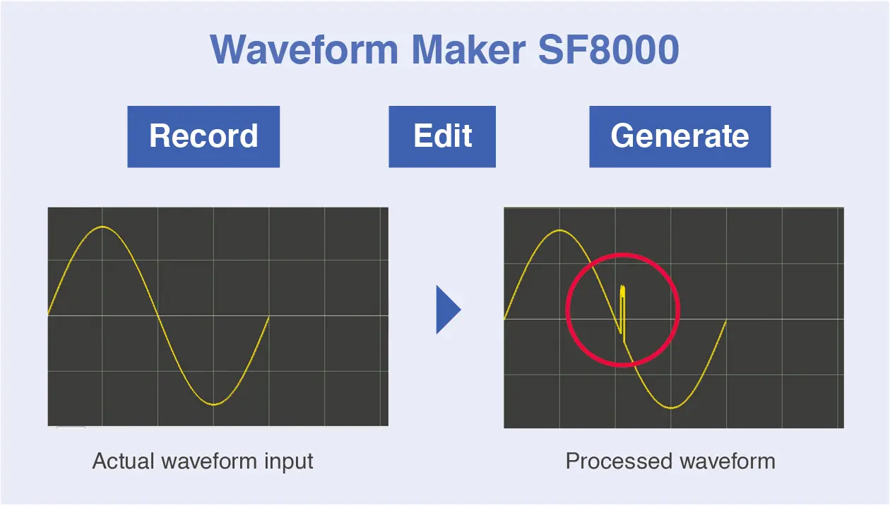
When real signals are unavailable or specific test conditions need to be created, custom signals can be designed directly on the MR6000 platform or using the SF8000 Waveform Maker software. This allows engineers to simulate precise waveform shapes and generate arbitrary signals for signal integrity testing and hardware-in-the-loop validation. They have full control over signal parameters such as waveform type, amplitude, frequency, and sequencing — particularly useful for scenarios that are difficult to reproduce in the field.
Example: A developer working on a throttle control system can simulate a progressive ramp signal. These custom inputs make it possible to evaluate performance, control behavior, and system stability under known and repeatable conditions. The generated signals can then be output via compatible signal generator modules, supporting a wide variety of test workflows — from simple functional checks to endurance and timing analyses.

3. Testing Edge Cases: Injecting Signal Anomalies
Another important application is the ability to modify recorded signals or design waveforms that intentionally contain anomalies such as voltage dips, sudden transitions, or noise pulses. This is essential for verifying system robustness under extreme or non-ideal conditions.
Engineers can replicate faults that are difficult to capture in the field, test reactions to power interruptions, or simulate conditions required for safety and reliability evaluations. By inserting anomalies, it becomes possible to better understand system behavior and robustness — whether the data comes from recorded measurements or freely created waveforms.
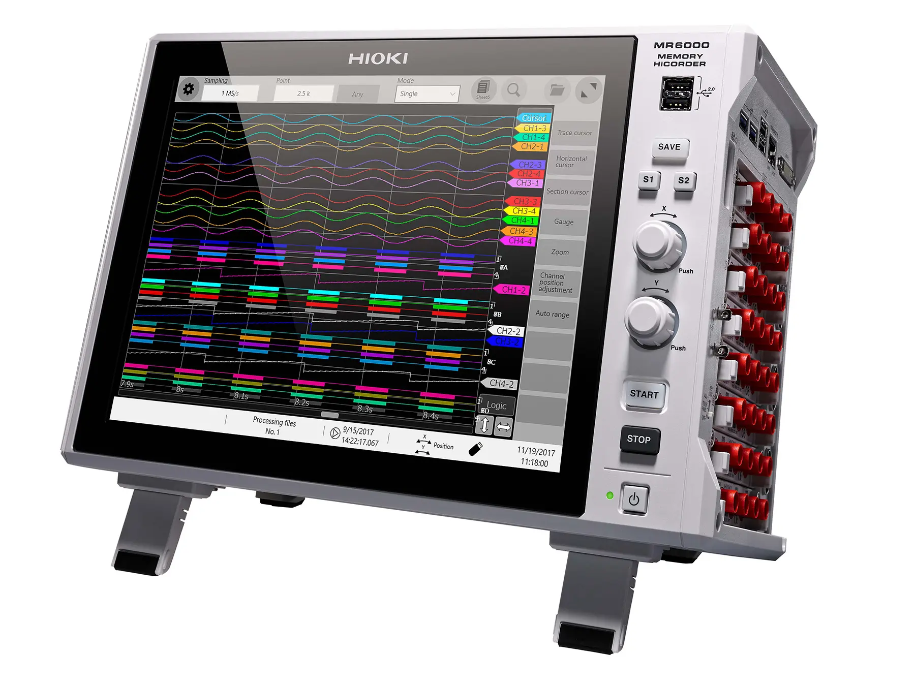
When acquisition, creation, and output are combined on a single platform such as the MR6000, test workflows become more consistent and efficient.


Depending on the signal type, the corresponding module and matching data recorder are used. Whether analog, digital, or sensor-like signals – HIOKI DAQ systems offer a solution compatible with every application.
- Analog signal waveforms, such as sine, pulse, or user-defined shapes, can be generated using an arbitrary waveform generator.
- To generate digital signals such as control pulses and logic patterns, a pulse generator is suitable.
- For realistic sensor outputs, including simulated voltage, current, and resistance, a dedicated sensor simulation module is recommended.
Module Overview: Signal Types, Modules, and Applications
| Signal Type | Module | Main Functions | Typical Applications | Compatible Data Recorders |
|---|---|---|---|---|
| Analog Signal Waveforms | U8793 Arbitrary Waveform Generator |
– Sine, square, pulse, ramp, triangle, arbitrary – ±10 V to +15 V, 10 mA – up to 100 kHz – 2 isolated channels |
Generation of arbitrary signal shapes, simulation of actuator signals, reproduction of recorded data | MR6000, MR8848, MR8827, MR8740T, MR8740, MR8741 |
| MR8790 Signal Generator |
– DC and sine only – ±10 V, 5 mA – 4 isolated channels |
Simulation of reference signals and injection of steady analog signals | MR6000, MR8848, MR8827, MR8740T, MR8740, MR8741 | |
| Digital Signals, Pulses | MR8791 Pulse Generator |
– TTL or open-collector output – 0.1 Hz to 20 kHz – 8-bit pattern output – 8 channels |
Testing digital logic, simulating control pulses, validating ECU signals | MR6000, MR8848, MR8827, MR8740T, MR8740, MR8741 |
| Sensor Signal Simulation | U8794 VIR Generator |
– Simulation of DC voltage, current, and resistance – 8 isolated channels – MR8740T only |
Simulation of sensor signals, analog input testing of ECUs, and verification of signal conditioning | MR8740T |
Explanation of the modules: With high flexibility and support for numerous signal types, the U8793 is particularly well suited for complex simulations of analog signals. The MR8790 is the straightforward choice for generating stable signals such as DC voltages or sine waves – perfect for reference voltages or basic analog input tests. The MR8791 specializes in digital signals, where precise timing control and pattern generation are required, for example when validating ECUs or control systems. All three modules can be used with tabletop data recorders such as the MR6000, MR8848, and MR8740T. This gives users maximum flexibility: they can choose between setups ranging from 32 to 108 channels, from compact stand-alone units to large integrated systems.
Designed specifically for sensor-like signal generation such as voltage, current, and resistance, the U8794 can be used exclusively with the MR8740T and is ideal for multi-channel applications and comprehensive ECU or sensor testing.
From Data Acquisition to Simulation: A Seamless Test Workflow
Why just record signals when you can do much more? By combining signal recording and generation on a single platform, test workflows become simpler and hardware complexity is reduced. This marks a clear step forward toward more efficient test processes. With HIOKI data recorders, real-world events can be captured, faithfully reproduced under laboratory conditions, and even extreme scenarios can be simulated – all on one platform.
This integrated approach shortens test cycles, minimizes errors, and ensures transparent results – from ECU validation and control signal simulation to endurance testing of embedded systems. It’s a modern, agile workflow that enables engineers to move from passive observation to actively controlling the test environment.


