Log in or Sign up
Exclusively for business customers in the EU, Norway, UK and Switzerland
Fast shipment from Germany
Go to homepage
Maintenance
  • Battery testers handheld
  • Clamp meters
  • Insulation resistance meters
  • Loggers & recorders
  • Multimeters
  • Power loggers
  • Power quality analyzers
  • Resistance meters handheld
  • More
R&D / Production
  • Battery testers
  • Current sensing
    • Signal analysis
    • Precision sensors
    • General sensors
  • Probes
  • Loggers & recorders
  • LCR meters / Impedance analyzers
  • Power measurement
  • Resistance meters
  • More
Accessories
  • Cases, bags & protectors
  • Test fixtures
  • Test leads & probe tips
  • Power supplies
  • Connection cables
  • More
SALE (- 20%)
Spare parts
Blog
Log in
or sign up
Overview Your profile Employees Roles Addresses Payment methods Orders
€0.00*
Need help?
Need help?
Do you have questions or require assistance?

Get in touch:

hioki@hioki.eu

Contact form

Show all categories Measuring Ultrafast Inverters with High Precision
Back Show Measuring Ultrafast Inverters with High Precision
  • Maintenance
  • R&D / Production
  • Accessories
  • SALE (- 20%)
  • Spare parts
  • Blog
  1. You are here:
  2. Home
  3. Footer
  4. Customer Service
  5. Blog
  6. Measuring Ultrafast Inverters with High Precision
  1. The reliability of many power analysers ends with SiC and GaN technologies
  2. Automatic Phase Shift Correction Minimizes Phase Errors
  3. Analysers and sensors work together precisely
  4. No room for error
  5. High-voltage dividers are the optimum solution for applications up to 5 kV
  6. Reproducible measurement results
  7. A measurement system from one source

Measuring Ultrafast Inverters with High Precision

Kai Scharrmann · 05.11.2024
Power Electronics | Automotive · 8 min. reading duration

Power analyzers produce increasingly incorrect, even impossible, measurement results when analyzing ultrafast SiC and GaN inverters. The solution are current sensors specif-ically developed for power analysis from a single source! For the first time, HIOKI's pow-er analyzers and sensors form a 100% matched power measurement system. This ena-bles automatic phase shift correction.

Measuring Ultrafast Inverters with High Precision
Kai Scharrmann
VP Sales, PM & Marketing, HIOKI Europe
Share post!

The advancement of inverters is a key factor in expanding electromobility and transitioning to renewable energies. Much depends on their ability to convert DC power from batteries and PV systems into usable AC power. Switching speed is an important metric. Another is efficiency. Specifically, in analyses of ultrafast SiC or GaN-based inverters, a peculiar phenomenon some-times occurs: it seems that more AC power is output than DC power is input. Such a physical paradox immediately stands out as an error. It is more challenging when a measurement shows a realistic but erroneous value. The goal is to avoid measurement errors like these. This is only possible with measuring instruments that meet the demands of new technologies. These are power measurement systems with reliable phase error correction.

Figure 1: Ultra-fast inverters are indispensable for progress in electromobility.

The reliability of many power analysers ends with SiC and GaN technologies

Phase errors have hardly any effect up to switching frequencies of around 10 kHz. Beyond this limit, however, many power analysers calculate incorrect efficiencies. With SiC-based inverters, tenfold switching frequencies of up to 100 kHz are now possible. GaN-based inverters even switch with a factor of 100 up to 1 MHz. As a result, commercially available power analysers produce unreliable measurements of the phase difference. They also use current sensors from third-party suppliers. The HIOKI solution always combines a HIOKI power analyzer with exter-nal HIOKI zero flux current sensors, which are designed for accurate power measurement and that have unique features to optimize high frequency power measurement. The most important feature the phase shift compensation function to reduce the influence of phase errors.

Figure 2: Complete solution: PW8001 Power Analyzer with HIOKI current sensors

Automatic Phase Shift Correction Minimizes Phase Errors

To correct measurement errors in the phase difference at high switching frequencies, HIOKI has developed a particularly effective phase shift correction for the PW8001 power analyser. For a phase shift compensation like that to work properly two things are necessary:

• A power analyzer that correctly performs phase correction

• A zero-flux current sensor with known time delay

Figure 3: Stable time delay of HIOKI CT68xxA current sensors

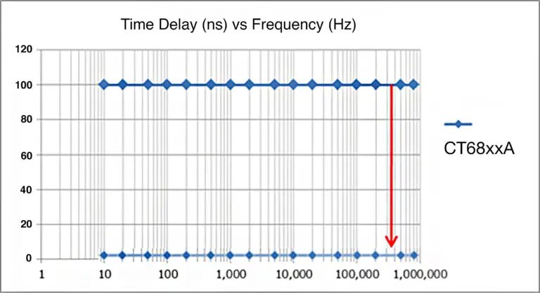
The new phase shift correction is comparable to the familiar deskew function in oscilloscopes: If two different signals arrive at the oscilloscope at different times due to latencies then the “deskew” function lets you align those signals by compensating the latency with a fixed time val-ue. The phase shift compensation is basically the same thing because the phase error is directly re-lated to the time delay of the current sensor. For a current sensor of the CT68xxA series from HI-OKI, for example, the delay is shown in Figure 3. You can see the time delay in nanoseconds de-pending on the frequency.

Figure 4: Phase delay as a function of the frequency

It is important to know: The 100ns delay at 100Hz doesn’t have the same impact as 100ns de-lay at 1MHz. This becomes clear when transforming the above time delay into phase delay values described in degrees:

Analysers and sensors work together precisely

To address this phase delay, HIOKI has developed its zero-flux current sensors together with its Power Analyzers. To efficiently compensate for phase delay, the time delay of the current sensor must remain constant regardless of the frequency. This is the case with the HIOKI current sen-sors that also communicate the value of the phase delay automatically to the power analyzer. In addition, the most important key figures of the current sensors are automatically transmitted to the Power Analyser via Plug & Play. That includes the sensor type, the serial number and the measuring range. The current sensor only needs to be connected to the PW8001 Power Ana-lyser in order to be used without errors and to automatically compensate for phase errors. Re-turning to the "deskew" function: Simply connecting the current sensor to the PW8001 power analyzer allows the phase error to be automatically compensated. 

The following behaviour can be observed with commercially available current sensors:

Figure 5: Conventional sensors compared to current sensors from HIOKI's CT68xxA series

With current sensors from other manufacturers, the time delay varies depending on the frequen-cy. Which value can be used as the “deskew” parameter? Phase shift correction is virtually im-possible with non-system sensors.

No room for error

Another feature that makes HIOKI current sensors unique is that the position of the wire core does not influence the phase delay:

Figure 6: HIOKI CT68xxA's phase delay and wire core position

The reason why you can only see one single line in the chart Figure 6 is because the phase de-lay curves for all five measurement positions are the same, which does not leave room for er-rors. Not all current sensors offer this feature as standard. As shown in diagram 7 below, the conductor position in the sensor has an effect on the phase error in third-party sensors.

Figure 7: Phase delay and conductor position with a typical sensor

High-voltage dividers are the optimum solution for applications up to 5 kV

If you are not only working with high frequency but also higher voltage applications, there is a solution that further covers this area: a highly accurate high voltage divider. With the capability to precisely measure power up to 5 kV, it represents a significant advancement in accuracy com-pared to existing solutions utilizing differential probes. This is particularly beneficial for high volt-age and high frequency applications involving SiC and GaN semiconductors because of its 4MHz bandwidth and a known phase error which makes it possible to compensate for the phase error in the power analyzer.

Reproducible measurement results

Repeatability of measurement results is essential to draw conclusions. HIOKI Engineers at our HQ in Japan have measured the efficiency of a SiC based inverter using the PW8001 Power Analyzer in combination with the 50A AC/DC current sensors CT6872 over a period of 30 sec-onds. The switching frequency of the SiC semiconductors was 50kHz, and the motor was at a constant speed of 1000rpm. The integration time for the measurement was set to 200ms and the motor current in this experiment was approximately 2A. The graph below shows the excel-lent stability of the measurement:

Figure 8: Efficiency measurement with a SiC-based inverter at 50 HZ excellent reproducibility

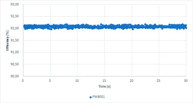
The difference between the maximum and minimum result during the 30 seconds was less than 0.2 %. This experiment demonstrates that even at low currents this setup delivers excellent re-peatability, which is key in the development stage because it enables to identify even small effi-ciency gains due to changes in the design. However, such accurate results can only be achieved with an effective phase shift compensation. Under the same test conditions two well-known suppliers of power measurement systems have been tested and the outcome is shown in figure 9:

Figure 9: Efficiency measurement with a SiC-based inverter at 50 HZ and bad reproducibility

In this case, the repeatability of the measurements is a lot worse. For both systems the differ-ence between the maximum and minimum efficiency is more than 1%. This makes it very hard for engineers to conclude if the changes they make in their designs have an effect or not. For instance, even if you measure an increase in efficiency of 0.9%, this might simply be caused by the poor measurement repeatability, and you might not have achieved an increase in efficiency after all.

A measurement system from one source

Effective phase shift compensation requires the combination of a power analyser with a phase shift compensation function and a current sensor with stable and known time delay characteris-tics at high frequencies. The PW8001 Power Analyzer even features automated phase shift compensation, allowing it to automatically recognize the current sensor and adjust the phase compensation accordingly using the data provided by the sensor.

Figure 10: Automatic sensor detection and retrieval of information by the power analyzer PW8001

HIOKI has been designing and producing current sensors for power measurement for many years and time delay characteristics have always been a design focus for the engineers. On the other hand, zero flux current sensors from other manufacturers are typically designed for accu-rate current sensing where time delay characteristics are less important. Therefore, only HIOKI power analysers in conjunction with HIOKI zero-flux current sensors measure high-frequency inverters with absolute precision. To measure efficiency accurately, both the DC input power and the 3-phase output power must be measured precisely.

Figure 11: From a single source: PW8001 power analyser and sensors from HIOKI

PW8001 - High Precision Power Analyzer PW8001 - High Precision Power Analyzer
PW8001
PW8001 - High Precision Power Analyzer
High-precision power analyser for analysing the efficiency of inverters and inverters with basic accuracy of ±0.03%, sampling rate of 15 MHz, 18-bit AD converters, automatic phase shift correction, data update rate of 1 ms.
CT6875A - AC/DC Current sensor CT6875A - AC/DC Current sensor
CT6875A
CT6875A - AC/DC Current sensor
The CT6875 AC/DC Current Sensor is designed for accurate current measurements across a broad frequency range, from DC to 2 MHz (Model CT6875-01: DC to 1.5 MHz). With a rated current of 500 A, it is ideal for R&D, quality evaluation, manufacturing, and maintenance in industries such as wireless charging systems, inverter motors, PV power conditioners, and EV quick charging facilities. In combination with the Power Analyzer PW8001, the sensor allows for precise high-frequency and low power factor measurements. Technical Details: Rated Current: 500 A Frequency Bandwidth: CT6875: DC to 2 MHzBasic Accuracy: Amplitude: ±0.04 % rdg. ±0.008 % f.s., Phase: ±0.08° Maximum Conductor Diameter: 36 mm Maximum Rated Voltage to Ground: 1000 V CAT III Operating Temperature: -40°C to 85°C Input Impedance Requirement: 1 MΩ or higher Output Terminal: ME15W Cable length: 3mMore than specs – find more details here:🔗 Measure Power with Precision – Across All Applications

€1,698.00*
CT6845A - AC/DC Current Clamp, Fluxgate, 500 A / 200 kHz CT6845A - AC/DC Current Clamp, Fluxgate, 500 A / 200 kHz
CT6845A
CT6845A - AC/DC Current Clamp, Fluxgate, 500 A / 200 kHz
AC/DC current clamp using advanced fluxgate technology, 500A rated current, basic accuracy ±0.2% rdg., wide temperature range of -40 °C to 85 °C, bandwidth from DC to 200 kHz, maximum conductor diameter 50 mm, cable length 3 m

€1,988.00*
CT6876A - AC/DC Current sensor CT6876A - AC/DC Current sensor
CT6876A
CT6876A - AC/DC Current sensor
Product Description for CT6876 AC/DC Current Sensor The CT6876 AC/DC Current Sensor is designed for accurate current measurements with a broad frequency range from DC to 1.5 MHz. With a rated current of 1000 A, it is ideal for demanding applications in industries such as inverter motors, electric vehicles, and power electronics.The sensor offers excellent noise resistance and high precision, making it a top choice for high-current, high-speed measurements. When combined with Hioki's Power Analyzers, it ensures accurate power conversion efficiency measurements, especially in high-frequency environments. Technical Details: Model: CT6876 Rated Current: 1000 A Frequency Bandwidth: DC to 1.5 MHzBasic Accuracy: Amplitude: ±0.04% rdg. ±0.008% f.s. Phase: ±0.1° Maximum Conductor Diameter: 36 mm Maximum Rated Voltage to Ground: 1000 V CAT III Operating Temperature: -40°C to 85°CInput Impedance Requirement: 1 MΩ or higher Output Terminal: ME15W

€2,268.00*
CT6844A - AC/DC High-accuracy Current Clamp, 500 A / 500 kHz CT6844A - AC/DC High-accuracy Current Clamp, 500 A / 500 kHz
CT6844A
CT6844A - AC/DC High-accuracy Current Clamp, 500 A / 500 kHz
AC/DC current clamp using advanced fluxgate technology, 500A rated current, basic accuracy ±0.2% rdg., wide temperature range of -40 °C to 85 °C, wide bandwidth from DC to 500 kHz, maximum conductor diameter 20 mm, cable length 3 m

€1,988.00*
CT6841A - AC/DC High-accuracy Current Clamp, 20 A / 2 MHz CT6841A - AC/DC High-accuracy Current Clamp, 20 A / 2 MHz
CT6841A
CT6841A - AC/DC High-accuracy Current Clamp, 20 A / 2 MHz
AC/DC current clamp using advanced fluxgate technology, 20A rated current, basic accuracy ±0.2% rdg., wide temperature range of -40 °C to 85 °C, wide bandwidth from DC to 2 MHz, maximum conductor diameter 20 mm, cable length 3 m

€1,818.00*
CT6846A - AC/DC High-accuracy Current Clamp, 1000 A / 100 kHz CT6846A - AC/DC High-accuracy Current Clamp, 1000 A / 100 kHz
CT6846A
CT6846A - AC/DC High-accuracy Current Clamp, 1000 A / 100 kHz
AC/DC current clamp using advanced fluxgate technology, 1000A rated current, basic accuracy ±0.2% rdg., wide temperature range of -40 °C to 85 °C, bandwidth from DC to 100 kHz, maximum conductor diameter 50 mm, cable length 3 m

€2,328.00*
Follow us
Measuring instruments & Accessories
  • Maintenance
  • R&D / Production
  • Accessories
  • SALE (- 20%)
  • Spare parts
  • Product Catalogs
Measurement solutions & tips
  • • Zero-Flux Current Clamps: from mA to kA​
  • • Wideband Current Sensors up to 500A & 120 MHz
  • • MR6000-MAX Memory Recorder Bundle​
  • • The Most Versatile Multi-Channel Data Logger​
  • • Precision Current Data Logging. Ultra-compact.
  • • Measure Power with Precision – Across All Applications
Blog Articles
  • • DC Current Measurement and Bandwidth​
  • • Zero-Flux Current Sensors: Like in “Back to the Future”?
  • • Your Path to Better Energy Efficiency: Current Mapping​
  • • Never Miss a Beat: Choosing the Right Sampling Rate for Data Acquisition​
  • • A dedicated resistance meter? Here is when it makes sense…​
Customer Service
  • About Us
  • Shipping & Returns
  • Where else to buy
  • Contact
Legal
  • Imprint
  • Terms & Conditions
  • Data protection
  • Battery disposal
  • Cookie settings
Payment methods
Credit Card (via Stripe)
Advance Payment
PayPal
Klarna (via Stripe)
© 2025 HIOKI EUROPE GmbH

* All prices excl. VAT plus shipping costs